-
Titolo
-
Aircraft Propellers Explained
-
Article Title and/or Image Caption
-
What You Should Know About Propellers for Our Fighting Planes
-
extracted text
-
AFTER a recent battle, American forces
captured a German soldier who kept
pointing upward and babbling about “big
whirling swords.” Some time later, doctors
discovered the cause of his hallucinations.
Lightning and Warhawk fighters had run
interference for the Yank advance by carry-
ing out one of their blistering strafing at-
tacks at tree-top altitude. The Nazi had
somehow escaped from his flaming tank and
survived the assault; but, in his fear, he had
psychologically identified the sunlit, spinning
propeller blades of the low-sweeping planes
as whirling swords.
Indeed, in a more practical manner, the
whirling prop blades of our warplanes do
symbolize their deadliness. The propellers
that pull our fighters and bombers—and
those of our allies—through the skies over
half a dozen war theaters are more than a
little responsible for the superb performance
that is affording American-made craft the
air superiority they now enjoy. The prop
is as much a part of the plane's power plant
as is the engine. It translates the engine's
power output into the “thrust” necessary for
sustained flight.
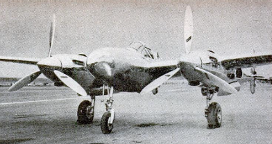
If we consider the propeller as a screw
working its way through the air and pulling
the plane along—or pushing it along, if it is
mounted aft of the engine, as in the case of
our Bell Airacuda and
some of the new push-
er-type fighters—just
as a steel screw bores
its way through a
piece of wood, the
principle of propulsion
is reduced to its sim-
plest terms. But, un-
like the screw, which
advances by pushing
the rear face of its
thread against the fi-
bers of the wood, the
prop advances by
creating just ahead of
its whirling blades an
area of suction into which they are drawn.
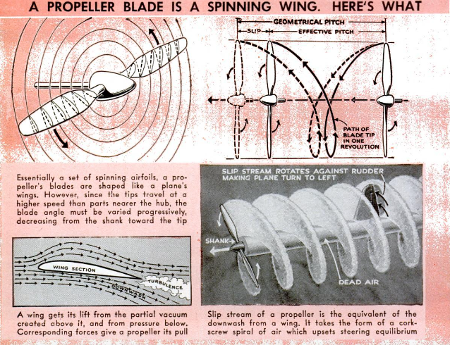
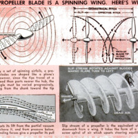
The propeller blades are shaped exactly like
the wing section of a plane and act on the
same principle. The prop is, to all intents
and purposes, a set of spinning airfoils.
Just as the airplane wing must move for-
ward fast to maintain its lifting properties,
the propeller must rotate swiftly in order
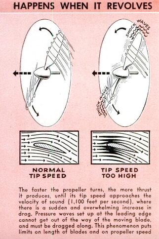
to provide thrust. The faster it turns, the
more thrust results—up to a certain point.
And, just as the wing is tilted upward slight-
ly in order to deflect the air downward (this
setting is called “angle of attack”), the
prop’s blades are twisted 50 as to deflect the
air rearward. This twist, or “blade angle,”
enables the blades to meet the air at an an-
gle that is most favorable for thrusting ef-
ficiency.
In rotating, the tips of the propeller must
travel around their greater radius within
the same time that the prop hub completes
a revolution. The tips, therefore, travel
may times faster than the center of the
prop. For this reason, the blades are not
straight like a wing but twisted so as to
permit the blades to meet the air at the
optimum angle along the entire length of
the propeller. The twist is most noticeable
in the inner half of the blade. Within a foot
or 50 of the hub, the blade merges from its
flat shape into a round, thick section that
provides no thrust whatsoever.
The very same laws of physics which per-
mit a wing to lift or a propeller to thrust
have decreed that we must pay a price for
these aeronautical services. The steepest
of these prices is drag. It is with drag that
the propeller must struggle constantly as it
pulls or pushes the plane through the air.
Drag acts on the prop in the same way as
on the wing, only more so because of the
high speeds at which the prop rotates. Drag
may be diminished by giving the wing sec-
tion or prop blade a more streamlined shape.
The new laminar-flow wing section—usedon the superb North American Mustang
fighter-bomber and other American craft—
has reduced drag almost 67 percent, and this
same type of airfoil section is used by some
of our propeller manufacturers.
Greater efficiency may also be achieved
by increasing the area of the blade to pro-
vide more thrust, but it is here that the en-
gineers encounter trouble. The diameter of
the propellers is limited by three considera-
tions: on single-engined craft, the prop
must be short enough to allow clearance
when the ship is on the ground on level keel.
On multiengined planes, ground clearance
is not such an important factor because
these ships are larger and sit higher, but
using bigger props means moving the en-
gines farther apart (and the outboard en-
gines farther out on the wing). When these
difficulties are overcome, there remains still
another: the larger the propeller’s diameter,
the higher the tip speed. When the tips of
the prop reach the speed of sound—1,100 feet
per second—they become literally barnacled
with a peculiar and exaggerated drag con-
dition called a “shock wave.” There are
limitations on the width of the blades, too.
As the blade is widened, it must be made
heavier for structural reasons, and this re-
sults in greater drag and weight. Compro-
mise is necessary for other reasons which
have to do with more involved aerodynamic
laws, and the product is the neatly tapered,
knifelike propeller blade we see on today’s
warplanes and airliners.
Notwithstanding these difficulties, the pro-
peller is just about the most efficient part of
the airplane. How it got that way is some-
what of a story. Some of the earlier props
were nothing more than twisted
airfoils, the blades being built
up of wooden ribs and covered
with cloth. Then they were
hewn out of a solid piece of tim-
ber. The first really serviceable
propellers were made of lami-
nated wood; these proved relia-
ble and aerodynamically efficient
throughout the crucial years of
aviation, and some of this type
are still used for small civil
planes and military trainers.
Early experiments with steel
propellers were conducted in
1917, prompted by maintenance
difficulties in World War I. Dur-
ing the next two years, several
hollow steel props were tested by the Army
Air Corps, and one solid steel model per-
formed satisfactorily. In 1921, earnest de-
velopment of the aluminum-alloy blade was
undertaken, and the ease of making blades
from solid stock, as compared with the ex-
pense of fabricating hollow steel blades by
the then available methods, made aluminum
more desirable. These dural blades and
hubs gained wide popularity, and the steel-
prop development lagged.
The improvement in performance and
durability brought metal propellers into al-
most universal use during the late 20's; the
most famous of these were the Hamilton
Standard and Curtiss Reed, both made of
dural. These props, of course, had a fixed
blade angle, or pitch. As long as aircraft en-
gines remained in the 500-horsepower brack-
et and 160 miles per hour was considered a
lot of speed, the fixed-pitch propeller was
adequate. As engines became more power-
ful and the demands for performance in-
creased, power-plant limitations were re-
lieved by the introduction of the adjustable-
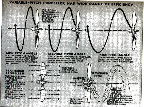
pitch prop, whose blades could be set to low
or high pitch—or a happy medium—and
clamped securely in the hub. In low pitch,
the plane had fine take-off and climbing
characteristics but was short on speed: in
high pitch, with the blades turned to meet
the air at a greater angle, the plane de-
veloped maximum speed but its take-off
and climbing ability was not what it might
have been. A compromise setting, however,
gave the craft good all-around performance.
As the pioneers had pointed out many
years before, what the flyer really needed
was a propeller whose pitch settings could
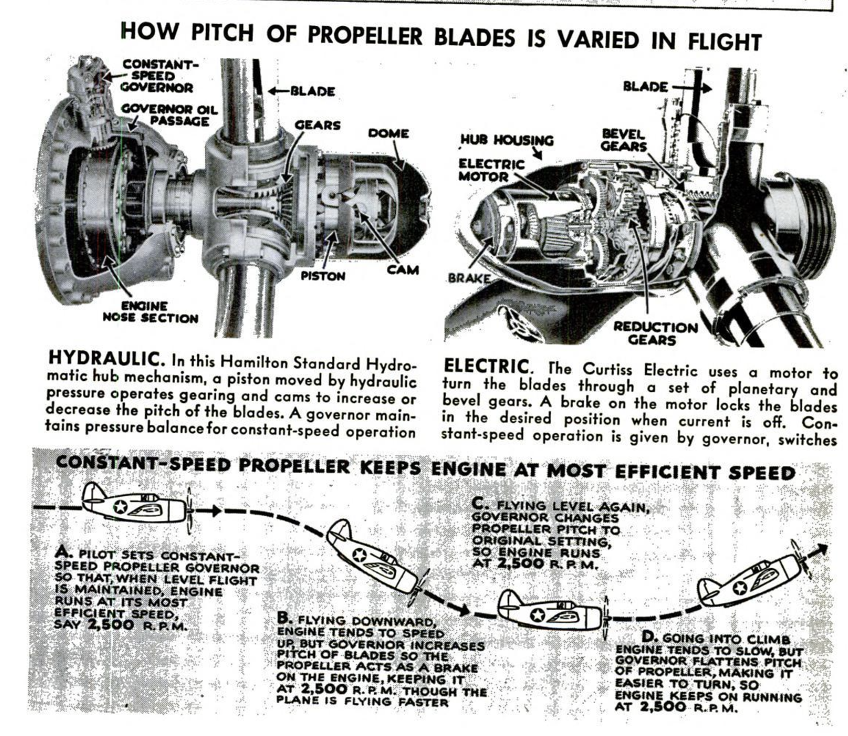
be changed during flight. In 1933, the Col-
lier Trophy was awarded to Hamilton Stand-
ard for the development of a successful
controllable-pitch propeller whose blades
could be set at high or low hydraulically
through a control in the cockpit that actu-
ated the hub mechanism. During the same
year, Curtiss perfected an electrically con-
trolled propeller. By taking off with the
prop blades in low pitch, fiyers got their
‘ships off the ground in 35 percent of the dis-
tance formerly required and increased their
rate of climb approximately 30 percent.
When they reached the desired altitude, the
shift was made to high pitch, with the re-
sult that top speed was increased almost 15
percent. For higher flights, an additional
20-percent increase in the plane's service
ceiling was obtained. The ingenuity of
Hamilton Standard and Curtiss-Wright en-
gineers greatly influenced airplane and en-
gine design by making possible the use of
larger and faster military craft and trans-
ports. The Lycoming-Smith electric con-
trollable-speed prop became popular for
lower-powered civil airplanes.
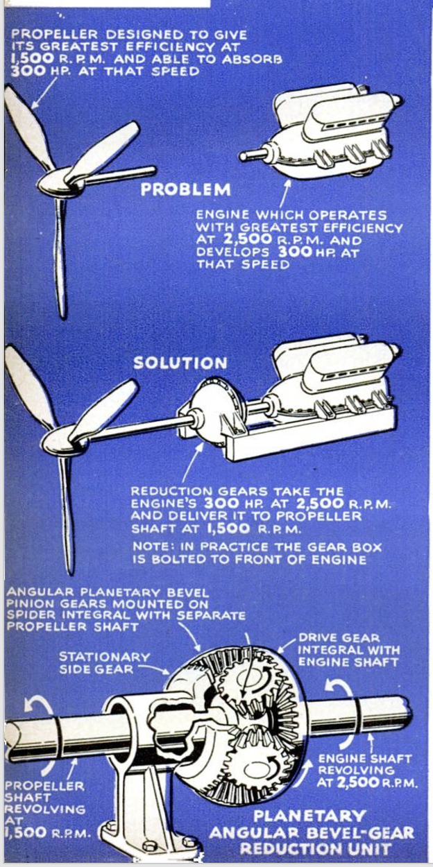
But with the advent of 1,000-horsepower
engines, this business of changing blade
pitch required further refinement. The en-
gine and prop have to be carefully mated;
for maximum performance, each has to
make concessions to the other,
and for every combination of
engine and propeller there is
an optimum speed for the two.
The engine's top power output
is gained at a constant r.p.m., or
crankshaft speed. This is gen-
erally higher than the propel-
ler's optimum speed, and reduc-
tion gears are set into the en-
gine nose section to slow down
the prop to three quarters or
half the engine speed.
In #s job of trandiatine the
engine's horsepower into useful thrust, the
prop also acts as a brake on the engine.
But this braking effect must be carefully
controlled or the engine will not function
at its best. The two-position propeller is
not sufficiently flexible in its operation to
absorb the output of today’s high-powered,
highly super-
charged engines, If the propeller were,
however, able to vary its blade pitch grad-
ually from zero-angle low pitch up to 90
degrees high pitch, it would be flexible
enough to absorb the engine's full horse-
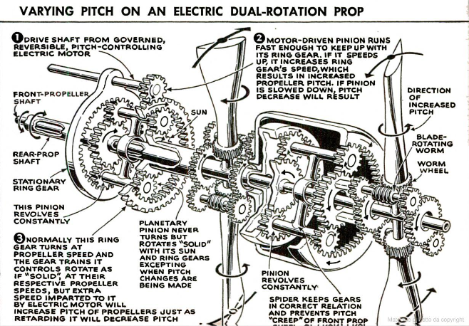
power at all altitudes. The constant-speed
propeller is such a type. The prop and en-
gine act as checks and balances against
each other under all conditions of flight.
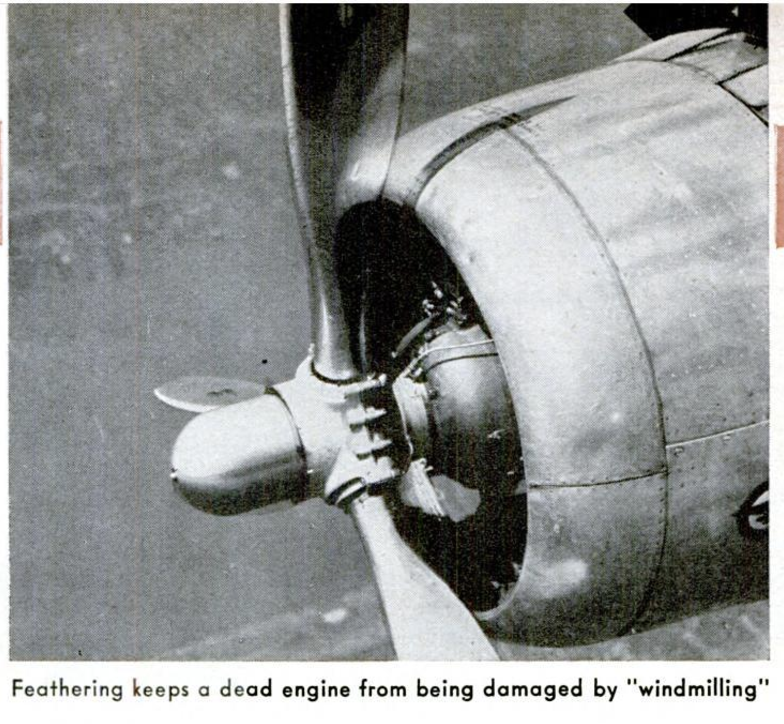
For emergency operation in the case of
multimotored airplanes, this business of
changing blade pitch has been carried a
step farther to permit the “feathering” of
the prop. The blades are turned in their
hub through highest pitch until they are
edge-on into the wind. The propeller is, of
course, useless for thrusting in this posi-
tion, but feathering is an expedient for fly-
ing with one or more engines out of opera-
tion, either by design or accident. Four-
engined transports frequently cruise on only
two of their engines, but this would not be
considered good flying practice if full-feath-
ering propellers were not available. Should
an engine go dead in an emergency, the
prop is feathered into the wind immediately;
the prop in this position acts as a brake on
the dead engine. In normal operating pitch,
the prop would be subjected to “pinwheel
ing,” just as the toy pinwheel spins when
held to the wind, and this might result in
a damaged engine. All the feathered pro-
peller does is create a drag. A windmilling
prop, however, would create more than 20
times this drag. The feathered propeller
adds about 1,500 feet to the service ceiling
of a twin-engined Douglas C-47 cargo trans-
port fiying on one engine and makes the
plane much easier to handle. Even a single-
engined airplane is at an advantage when
fitted with a feathering prop because, in
emergency, the plane's gliding range is half
again as great with this type as it would
be with a windmilling, unfeathered prop.
Carrying the pitch angle beyond the 90-
degree feathered position into reverse pitch
was a logical step in propeller development
made first by Curtiss-Wright. The reversi-
ble-pitch prop, Which delivers negative
thrust, is extremely useful as an air brake.
In some instances, it may be used to slow
the landing run of planes, but its most prac-
tical application is found ou multiengined
flying boats. Maneuvering a flying boat w
the water is, at best, a tricky operation.
The reversible prop facilitates maneuvering
in general and turning m particular. By
reversing the two inboard propellers and
leaving the outboard props in normal pitch,
the pilot of a four-engined flying boat can
“come about” in one-fourth the turning ra-
dius of a similar craft with conventional
propellers.
Under the most favorable conditions, the
prop is capable of translating 86 percent
of the engine's horsepower into useful thrust,
and props have a specific weight of between
22 and .38 pounds per horsepower. (There
are only three or four aircraft engines in
the world that are known to have a weight-
horsepower ratio of less than one pound per
horsepower.) It is because there is so lit-
tle room for improvement that propeller en-
gineers are burning up much midnight ofl
and energy in their quest for increased pow-
er-plant berformance.
It has been mentioned that the adapta- |
tion of the laminar-flow airfoil section
which holds the stream of passing air close
to the surface and cuts down turbulence
and drag to prop blades increased their |
efficiency, and that engineers have sought to
increase the blade area to gain more thrust
and absorb the output of higher-horsepower
engines, The compressibility phenomenon
of the shock wave makes the engineers host.
fate to. Mereate blade diameter. Bigger
‘props could be used only if they were geared
Gown to turn slowly enough that the tips
would not reach the speed of sound. When
an airfoil attempts to exceed this speed, the
pressure wave created at its leading edge
Cannot move ahead of the airfoil, The com.
pressibility cannot get out of the way of
the wing or propeller and must be carried
along with i, Just as the bow wave of a
Steamer Is cast upward instead of outward
‘along. the surface when high speed is at-
tained. Unlike the much denser water, the
air has nowhere to go and must be dragged
along, coating the. propeller with tightly
Packed, turbulent air that does nothing but
Create buch drag that the airfoil loses much
Gf ita thrusting ability.
Hamilton Standard engineers increased
their blade aren without extending the diam-
eter by making the blade paddle-shaped
from the shank outward. The paddle blade
a wider, with & more founded tip, and is |
stil structurally strong enough at the shank
to withstand the many stresses. There is,
However, a limit to the width of the biade.
The ability to absorb the engine's power fn.
creases directly in proportion to the width
of the blade, but, unfortunately, the weight
Micreayes with the sgtare of the Width, |
When the blade is made thicker, it dis-
places more air and builds up compressibility
more readily.
There are still other more involved limi-
tations. One of these was the problem of
cooling the radial-type engines, since the
slip stream, or backwash of air from the
prop, is hollow in the middle because of the
blades’ shape. This was overcome by fit-
ting the blades with cuffs that continue the
airfoil shape right down to the hub. This
additional surface provides larger thrust
area and also brings the hole in the center
of the slip stream down almost to nothing.
Part of the backwash is then able to enter
the engine cowl and contribute to cooling.
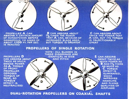
The next obvious step in gaining thrust-
ing area was the use of more blades. When
planes began to use the bigger engines, the
demand for more than three blades forced
engineers to solve the vibration problems in-
troduced by four- and six-bladed props.
Four-bladed propellers of wood were used
in World War I, and were reintroduced by
Curtiss in hollow steel form in 1939. Planes
that use four-bladed props include the Mar-
tin Marauder, Republic Thunderbolt, North
American Mustang, and Britains Spitfire
IX (with a British Rotol prop).
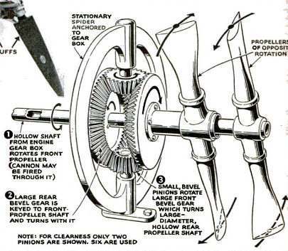
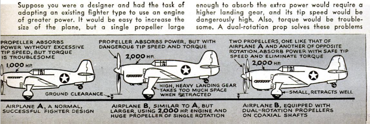
The ultimate in props today is the four-
or six-bladed dual-rotation job, which con-
sists of two units mounted on coaxial shafts
which turn in opposite directions. Even these
have been fitted with constant-speed, feath-
ering hub mechanisms by Curtiss, Hamilton
Standard, and General Motors, and by Ro-
tol and De Havilland in Britain. They are,
literally, two propellers and naturally are
heavier than a single prop. But because they
can be of smaller diameter and blade width,
the weight is not actually doubled but is
only about one third greater. The dual-ro-
tation props are worth their weight in per-
formance. First of all, they do away with
the evils of torque, or swinging action in
flight, since the torque of one set of blades
cancels out that of the other unit. Shorter
landing gears can be used because of the
smaller blades, and this results in a great
saving of weight and improved landing be-
havior of the plane. At speeds around 400
miles per hour, the contra prop increases
aerodynamic efficiency more than five per-
cent. The rear prop picks up the whirling
slip stream of the forward set of blades
and converts it into useful thrust.
The engineers are hard at work on still
newer ideas, but the dual-rotation prop
will be with us for many years to come.
-
Autore secondario
-
James L. H. Peck (writer)
-
Stewart Rouse (illustrator)
-
Lingua
-
eng
-
Data di rilascio
-
1943-11
-
pagine
-
122-127, 212, 216, 218
-
Diritti
-
Public Domain (Google digitized)
-
Archived by
-
Matteo Ridolfi
-
Alberto Bordignon (Supervisor)
 Schermata 2022-10-18 alle 15.47.50.png
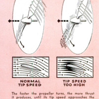 Schermata 2022-10-18 alle 15.47.57.png
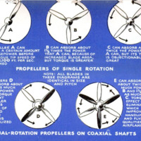 Schermata 2022-10-18 alle 15.48.02.png
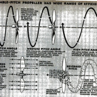 Schermata 2022-10-18 alle 15.48.09.png
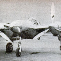 Schermata 2022-10-18 alle 15.48.15.png
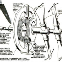 Schermata 2022-10-18 alle 15.48.22.png
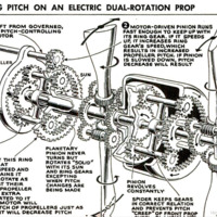 Schermata 2022-10-18 alle 15.48.28.png
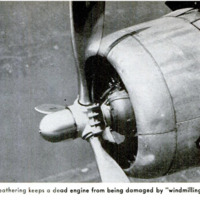 1.png
1.png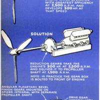 2.png
2.png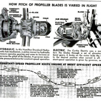 3.png
3.png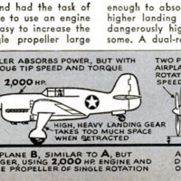 4.png
4.png