-
Title (Dublin Core)
-
Jet-turbine planes the race of the turbo-jets
-
Article Title and/or Image Caption (Dublin Core)
-
Title: Jet-turbine planes the race of the turbo-jets
-
extracted text (Extract Text)
-
ENGINES that deliver both jet and pro-
peller power have been developed be-
hind the veil of wartime secrecy. While the
atom smashers were tapping a new source
of heat, the aviation engineers were seeking
new, more efficient means of using heat to
fly airplanes—and their discoveries can be
used immediately.
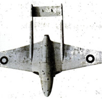
Already, the new-type engine's perform-
ance is being evaluated in an experimental
AAF plane soon to be test-flown. This air-
plane differs from all others in that a gas
turbine both pulls and pushes it through the
air. The P-80 Shooting Star and the British
Vampire are merely jet planes. The Ryan
FR-1 Fireball has a conventional engine in
its nose and a jet engine in its tail. The
new fighter has a gas turbine that twirls a
prop in the nose and a turbo-jet engine that
emits a jet in its tail.
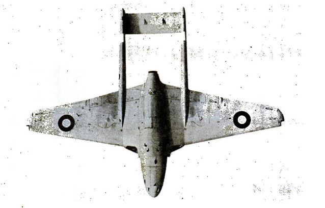
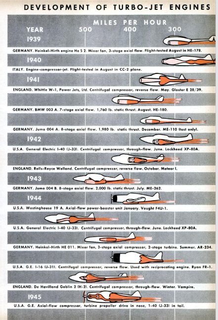
Jet propulsion is such a momentous de- |
velopment that May 14, 1941, the date the |
first British jet fighter flew, already ranks
second in importance in aviation history
only to December 17, 1903, the date of the |
Wright brothers’ first flight. That fighter |
had a W-1 turbo-jet, designed by Frank
Whittle, and was built by Power Jets, Ltd.
It proved that, at long last, airplane speeds
were high enough, heat-resistant alloys were
good enough, and the installed weight of |
power units plus fuel was low enough to
permit the gas turbine's use in aircraft. |
The turbo-jet engine, as is now well
known, operates by pulling in air, compress- |
ing it, and adding heat at high pressure.
Some of the energy resulting from the ex- |
pansion of the combustion products turns |
the turbine that drives the compressor; the |
rest can be ejected through a nozzle at high |
velocities. The reaction to this high-pow-
er discharge of
such a jet will thrust an airplane forward.
Such turbo-jets differ from rocket engines
(P.S.M., May "45, p. 70) in that they rely on
the atmosphere rather than their fuel sup-
ply for oxygen. They are most efficient at
very high speeds and altitudes. At low
speeds and altitudes, too much of their
thrust power is needed to turn the turbine
which pulls in and compresses the air. By
using two gas turbines, however, one to emit
a jet and the other to turn a propeller, air-
craft can be operated efficiently at either
high or low speeds and altitudes. “The gas
turbine,” says Dr. Jerome S. Hunsaker,
head of the department of aeronautical and
mechanical engineering at Massachusetts
Institute of Technology and chairman of
the National Advisory Committee for Aero-
nautics, “gives evidence of being the next
step in the evolution of power plants, com-
parable in its effect on technology to that of
the steam turbine at the turn of the cen-
tury.”
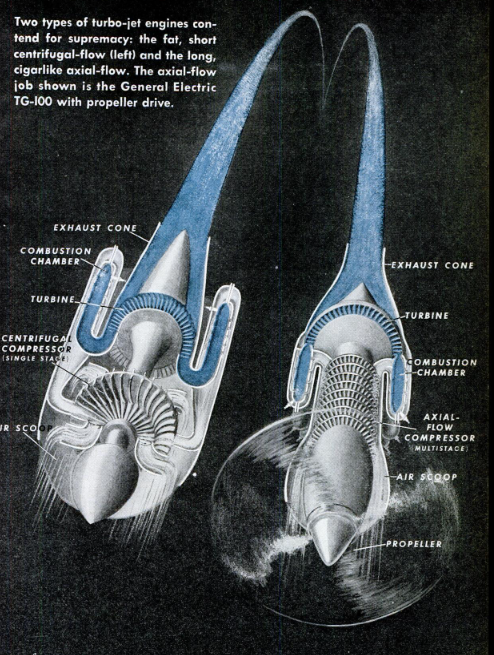
There are two important types of turbo-
jet engines, operating on the same funda-
mental principles but differing in the ar-
rangement of the essential parts. One type
is the centrifugal-flow turbo-jet, and the
other is the aial-flow turbo-jet. The dif-
ference is somewhat analogous to that be-
tween conventional radial and in-line re-
ciprocating engines. A centrifugal-flow
turbo-jet is likely to be short and fat like
a drum, whereas an axial-flow engine may
be long and thin like a cigar.
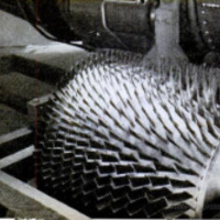
Centrifugal-flow engines, based on Cap-
tain Whittle's original conception, pull the
air in near the center and whirl it out
toward the ends of the compressor blades.
The rear casing of the air compressor may
have seven, ten or more symmetrical chan-
nels radiating outward, depending on the
number of combustion chambers. These
channels distribute the air to the chambers
where it is mixed with the fuel.
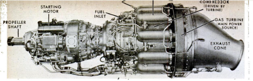
In the axial-flow engines, on the other
hand, the air flows straight through the
five essential parts of a turbo-jet: (1) in-
take duct, (2) compressor, (3) combustion
chamber, (4) turbine, and (5) exhaust noz-
zle. These parts are arranged in a straight
line in axial-flow engines, and compression
is obtained by the action of several sets of
blades rather than by the single-stage ac-
tion usually found with centrifugal flow.
Advocates of centrifugal-flow engines
rightly contend that greater power per
pound of the engine weight has been ob-
tained thus far from engines of this type
than from axial-flow engines. The latter,
however, being smaller in diameter, are
cleaner aerody-
namically and better suited for installation
in high-speed aircraft.
‘The Germans concentrated almost wholly
on development of axial-flow engines—and
came dangerously close to winning the be-
hind-the-scenes battle of the aeronautical
engineers. Ernst Heinkel, one of their most
versatile engineers, and his firm became in-
terested in jet propulsion in the late 1920s;
research work began at the Bavarian Motor
‘Works near Munich in 1934, and at the huge
Junkers works at Dessau in 1937. Test
flights were made with jet planes in Ger-
many before Whittle’s motor was tried in
the British Gloster, although his original
unit was run earlier on test stands.
German plans called for the development
of huge aircraft of the flying-wing type,
powered by turbo-jets. Supersonic aircraft
with ram jets, and accurately controlled,
long-range, guided missiles, were also pro-
jected. Basic research for these machines
was largely completed by the summer of
1945, when Allied technical experts poured
into Germany. Their findings give point to
the Nazis’ boast in 1940 that their military-
aircraft program was well in hand for six
or even eight years to come. They had the
men, the money, and the research facilities,
and came disturbingly close to success.
British engineers at the Royal Aircraft
Establishment had also begun work on axial
compressors and gas turbines in the 1930's,
but it was Whittle's centrifugal-flow type
that really sparked the production program
in England. While the test flights were
being made in 1941, a more advanced Whit-
tle unit, the W/1A, was being run on test
stands—and this engine became the basis of
the first American operational units. :
A Whittle engine, built by Rolls-Royce
and called the Welland, powered the British |
Gloster Meteor, the twin-jet fighter that
was used successfully to combat the V-1
flying bombs in the summer of 1944. Mean- |
while, Major F. B. Halford, chief designer
of De Havilland’s aero-motor division, de-
signed a more powerful turbo-jet which be-
came the power plant of the De Havilland
Vampire, Britain's speediest jet fighter, with
a top speed of 540 miles per hour.
Colonel Donald J. Keirn of Wright Field
went to England in the summer of 1941 and |
returned with one of the first Whittle W/1A
units. General Electric then produced the
1-A turbo-jet and greatly improved it as |
the I-16. Its top speed of 414 miles per hour
in the Bell jet fighter was less than that of
the P-47 and P-51 with boosted reciprocat-
ing engines. It was essential that the Allies
have a fighter with a jet speed 100 miles
per hour higher than that. So Wright Field
asked General Electric to produce a larger
and more powerful turbo-jet based on the
Whittle design. At the same time Lock-
heed was asked to design a suitable air-
frame to take a more powerful unit.
As a result of this high-pressure de-
velopment, the XP-80A with GE I-40 turbo-
jet was test-flown in June 1944. This was
the Shooting Star, still the fastest plane in
the air.
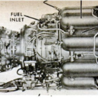
The I-40 turbo-jet is the most powerful
aircraft engine in production. With its mag-
nesium compressor housing, it weighs 1,850
pounds, compared with 828 pounds for the
I-16, and has 14 radially arranged combus-
tion chambers instead of 10. The I-40 em-
bodies the “through-flow” rather than ‘“re-
verse-flow” feature of the I-16, Welland,
and early Whittle designs, and this permits
a diameter only seven inches greater than
that of the I-16. Sea-level static thrust is
2 1/2 times greater than that of the smaller
engine.
In addition to these developments of cen-
trifugal-compressor-type turbo-jets, a group
of engineers has been working for several
years on the design and development of
axial-flow gas turbines for jet propulsion
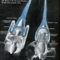
and for propeller drive. The first project to
be completed was the unit for propeller
drive, which underwent its first test-stand
run in the spring of 1943. In June 1945, the
first unit was installed in the experimental
fighter mentioned at the beginning of this
article. This is an all-gas-turbine job, with
a propeller turbine in the nose (TG-100,
newly designated XT-8) and a turbo-jet
(I-40, or J-33) in the tail for fast take-off,
accelerated climb, and combat booster
power.
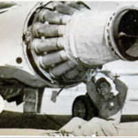
The General Electric axial-flow turbo-jet
unit (TG-180) was developed in 1943, and
was first run on the test stand in April
1944. It is the projected power plant of sev-
eral experimental fighters and bombers that
are well distributed throughout the Ameri-
can aircraft industry. Both this unit and
the gas turbine for propeller drive should
also be suitable for use in long-range trans-
port aircraft.
-
Contributor (Dublin Core)
-
Col. N. F. Silsbee (article writer)
-
Language (Dublin Core)
-
Eng
-
Date Issued (Dublin Core)
-
1945-12
-
pages (Bibliographic Ontology)
-
76-79,234,238
-
Rights (Dublin Core)
-
Public domain
-
Archived by (Dublin Core)
-
Sami Akbiyik

 Popular Science Monthly, v. 147, n. 6, 1945