-
Titolo
-
Putting More Speed and Power into Our New Navy
-
Article Title and/or Image Caption
-
Putting More Speed and Power into Our New Navy. Tests on models in huge towing basin show how to build the superships of tomorrow
-
extracted text
-
THE Navy's newest and
most spectacular research
plant, the David Taylor Mod-
el Basin at Carderock, Md., is
today right in the thick of
the war, going full blast on a
host of specialized problems
raised by actual combat ex-
perience. Lessons learned in
battle are being translaced
into new and better designs
for fighting ships and trans-
ports. They are leading to
more speed and deadlier wal-
lops that are already being
felt by our enemies.
Functioning also as trouble-
shooter, the basin staff swings into action
whenever an American ship reports its
power system, maneuverability, structure,
or general seaworthiness not up to muster.
When they are not tackling some ticklish
design job, these naval architects and en-
gineers are hard at work improving sub-
marine nets, devising underwater targets,
or solving a thousand and one other prob-
lems that have cropped up during the war
at sea on all our far-flung fighting fronts.
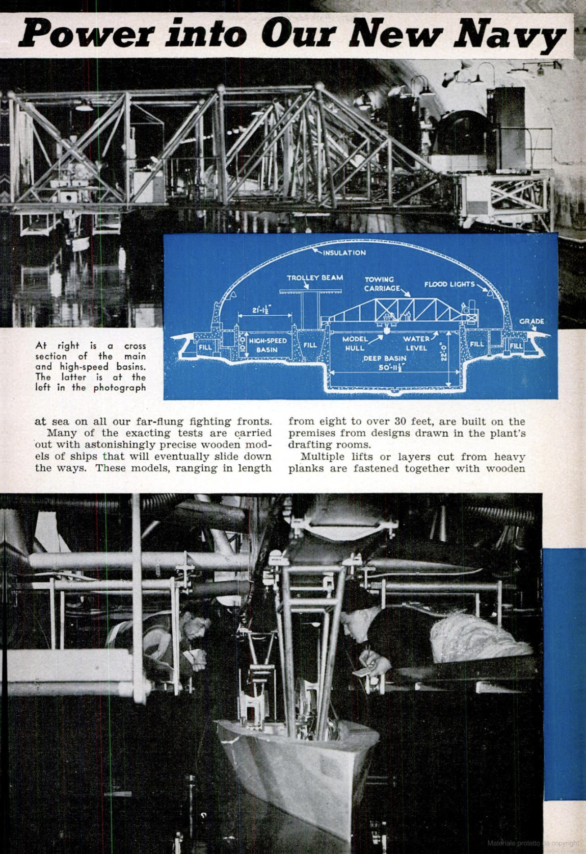
Many of the exacting tests are carried
out with astonishingly precise wooden mod-
els of ships that will eventually slide down
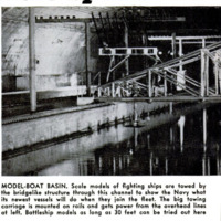
the ways. These models, ranging in length |
from eight to over 30 feet, are built on the
premises from designs drawn in the plant's
drafting rooms.
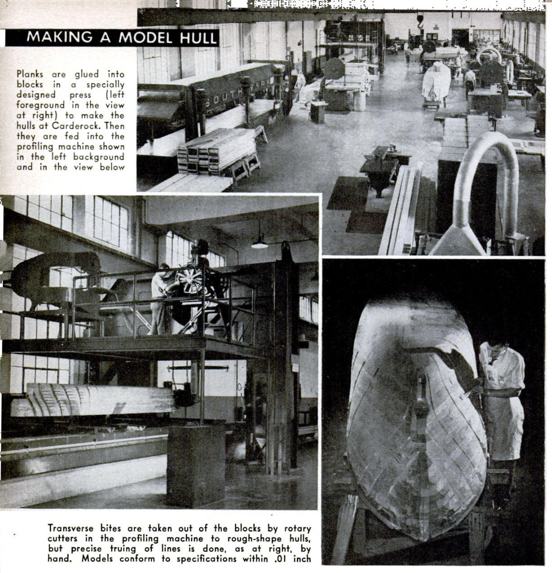
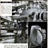
Multiple lifts or layers cut from heavy
planks are fastened together with wooden
dowels and hot, waterproof, resin glue, then
consolidated into rigid blocks in a glue press
capable of exerting a pressure of 1,200,000
pounds. These blocks are fed into a model-
profiling machine, where rotary cutters take
transverse bites. Precise truing of hull lines
follows by hand.
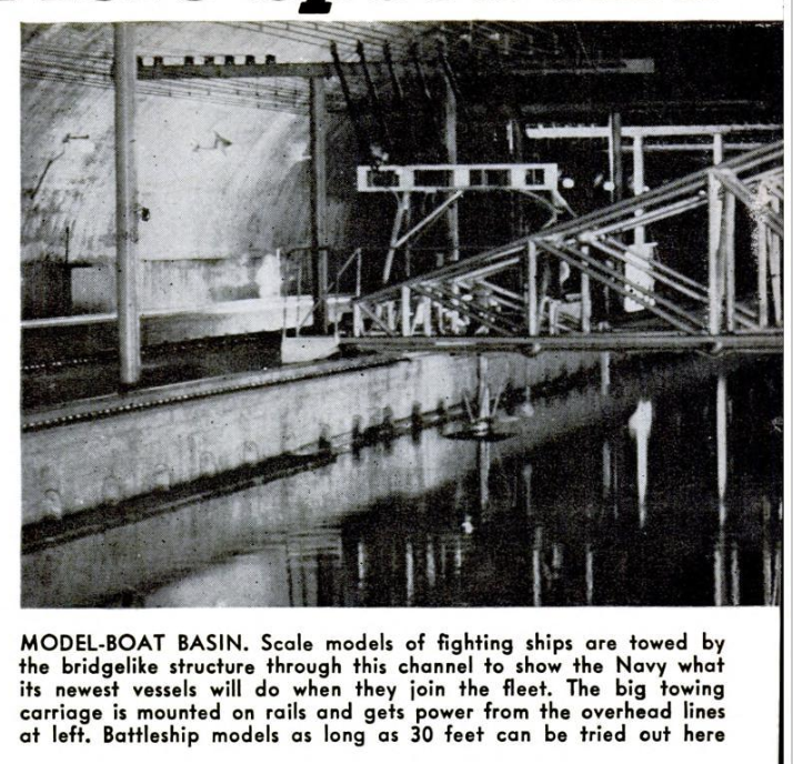
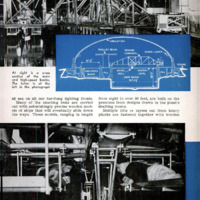
Once completed, a model is floated through
a channel into a 1,330-foot testing-basin
building that is the heart of the whole plant.
The huge tunnel-like enclosure has a barrel-
arch roof of reinforced concrete hinged at
three places to allow for expansion or con-
traction.
Along one side runs a deep-water basin,
big enough to accommodate models of the
largest battleships; extending out from it,
beyond a caisson, is a shallow basin for
models of tugboats, river boats, and kindred
vessels. Should the towing carriage on the
deep-water basin need an added run to work
up speed for special tests, the caisson can
be removed, allowing the shallow channel
to serve as a runway.
The shallow basin also connects with a
U-shaped turning basin used to test the
turning and maneuvering characteristics of
a model. For this the towing carriage
speeds up along the shallow basin on a
straight run and releases the model, which
is propelled around the bend under the
guidance of its own rudder. The entire tun-
nel is plunged into darkness, and movie
cameras on an elevated platform follow tar-
get lights to record the movements.
Finally, there is a high-speed basin where
models of motorboats, seaplanes, high-speed
vessels, pontons, and friction planes are
put through their paces. This channel, now
21 feet wide, 10 feet deep, and 1,168 feet
long, will eventually be extended to about
2,400 feet. Its towing carriage is designed
to hit a maximum speed of 30 knots.
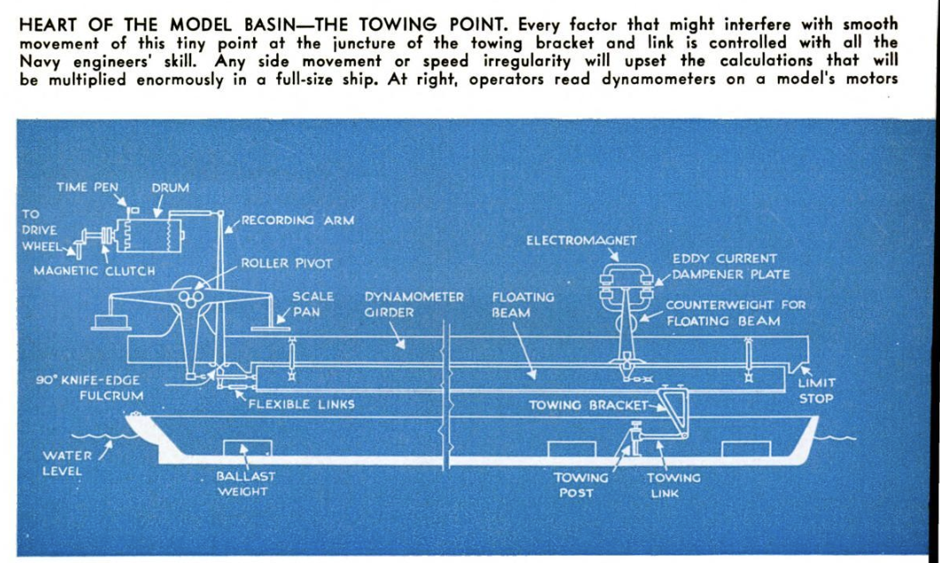
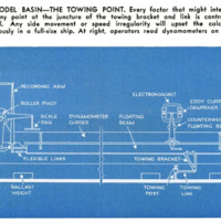
These towing carriages are real engineer-
ing feats. The chief headache in setting up
a model basin is to build all the parts in-
fluencing the towing point to such close tol-
erances, and then to control their warp and
wear so painstakingly, that the towing mo-
tion will remain uniform throughout. Any
side movement or speed irregularity will
upset the results registered on sensitive dy-
namometers that measure resistance, torque,
and thrust, and what looks like an incon
sequential discrepancy in the model may
loom as an error of the first magnitude in
a full-size vessel. For this reason, models
built in the basin’s shops conform to speci-
fications within .01 inch, whereas a large-
scale ship may deviate from design dimen-
sions by as much
spe as six inches.
Every factqr that
might "conceivably
interfere with the
smooth running of
the towing point is
controlled with all
the skill Navy en-
gineers can muster.
First of all, the re-
inforced concrete
walls on which the
carriage rails rest were carried down to
bedrock, The tracks themselves are mi-
racies of precision machining And track.
laying skill. Vertical variation nowhere ex-
coeds plus or minus .005 iach, nor is lateral
Variation any greater.
Fitted into position with microscople and
electrical checks, the tracks are fastened so
securely that the vertical deflection in the
top surface of any rail when # carriage
wheel passes over or adjacent to a given
point 1s never more than 001 inch. If you
Were riding on a raflroad train over tracks
of such precision, you would actually not
be aware of movement, so smoothly would
you be traveling.
The Carderock rails were even laid to
follow the curvature of the earth's surface
#0 that the influence of gravity would re.
main constant. It took upwards of 15
month Just to complete these runways, but
in return for their pains Navy engineers
ot & towing point which, when the building
bas settled firmly, may yield dynamometer
readings accurate to 01 pound.
“The larger of two towing carriages span-
Ding the deep-water basin 1s a weird mesh
of silvery tubes, fantastic enough to_ give
Buck Rogers an inferiority compiex. Some
of these pipes come together at 10-member
spherical Joints, and all enclose one vast
Connected space which is emptied of air and
filed with nitrogen to prevent corrosion.
The network Itself Is constructed in the
form of an isosceles triangle. with ts base
running along the main rail and its apex
resting on the steady rail
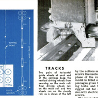
"The" track system is virtually monorail
for the carriage's center of gravity is close
to its base, and the greater burden of its
welght—72.800 out of 85,400 pounds rests
on the main rail, supported by four flange-
less driving wheels attached to the base
girder. There are also four pairs of horl-
zontal guide wheels which bear against op-
posite sides of the rail head and keep the
vertical driving wheels from swerving. The
carriage can be accelerated and decelerated
with amazing smoothness and leveled off to
uniform motion at speeds as low as .1 knot.
‘The designers’ goal was a speed that would
show no variation greater than 01 knot
under operating conditions.
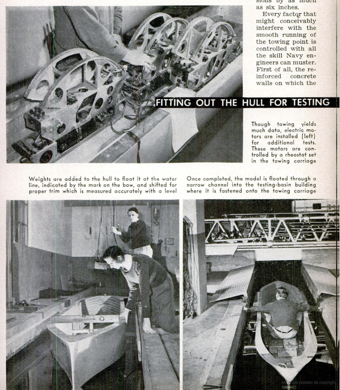
In operation, a model, sometimes weigh-
ing as much as 3,000 pounds, is fastened to a
towing link and bracket hanging down from
a towing dynamometer of the floating-frame
weighing type. Starting at one end of the
basin, the carriage gradually attains the
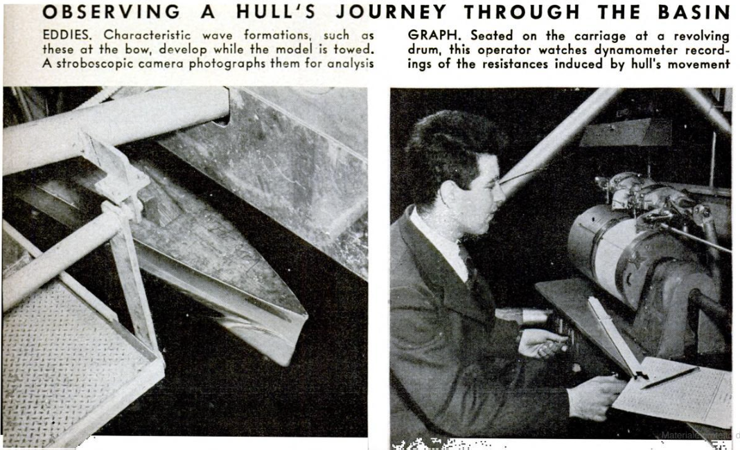
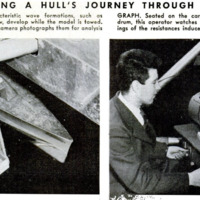
speed required. As it is towed, the model
develops its characteristic wave formation
and induces & steady flow of water in con-
tact with its wetted surface. Wave forma
tions may be recorded for analysis by a
stroboscopic camera, while resistance is
registered on the dynamometer.
In determining the power required to
drive a ship at a given speed, two types of
resistance must be considered. Frictional
resistance, induced between a hull's wetted
surface and the passing water, accounts for
‘most of the resistance at low speeds. But
at higher speeds another type of resistance,
called “residuary,” due chiefly to waves pro.
duced at bow and stern, becomes extremely
important. Carderock engineers, by sub-
tracting frictional resistance from the total
resistance registered on their dynamome-
ters, arrive at the residuary resistance,
which Is markedly affected by the hull con.
tours they are studying.
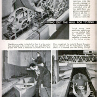
However, towing the bare hull will not
yield all the essential data about a model
it must also be ascertained how resistance
i Increased by the drag of eddy currents
around bilge keels, propeller-shatt supports,
rudders, and other projections, as well as
by the actions set up by the
screws themselves. For this
phase of the research, the
model is fitted out with ap-
pendages, given further tow-
ing tests, and then finally
rigged out for self-propul-
sioa with electric motors and
screws.
‘The speed of these motors,
which also function as dynamometers to
register torque and thrust, is controlled by
a rheostat operated by the man at the car-
riage's recording mechanism. This opera-
tors job is to bring about a balance between
the model's speed and the speed of the car-
riage, so that the model will be entirely un-
der its own propulsion during the register-
ing period although it remains attached to
the towing point. When
this balance has been at-
tained, two more opera-
tors, lying on platforms
near the water's surface,
take readings from the
dynamometer scales on
top of each motor.
To round out their pic-
ture of new ship designs,
Carderock experts en-
gage in a whole series of
supplementary studies.
They have a 142-foot
model basin in which they
can test special forms,
stability, launching, and
unusual hydrodynamic
problems. They are per-
fecting plans for a 60-
foot circulating water
channel for keeping a
model stationary while
they observe it through
a glass window.
-
Autore secondario
-
Bernard Wolfe (writer)
-
Robert F. Smith (photographer)
-
Lingua
-
eng
-
Data di rilascio
-
1943-06
-
pagine
-
82-87
-
Diritti
-
Public Domain (Google digitized)
-
Archived by
-
Matteo Ridolfi
-
Alberto Bordignon (Supervisor)