-
Title (Dublin Core)
-
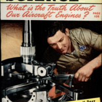
The Truth About Our Aircraft Engines
-
Article Title and/or Image Caption (Dublin Core)
-
The Truth About Our Aircraft Engines. The finest airplane power plants in the world today are carrying our flyers to victory. Here's the story of these superb machines and the big job they do
-
extracted text (Extract Text)
-
MERICAN airplanes are winging their
/N way over every theater of war in
the spring offensive that is hacking
at the heart and the outspread tentacles of |
the Axis octopus. With our flyers or those
of our allies at the controls, greater num-
bers of U.S. warplanes are in the air than at |
any other time in history; and, more than
any other single factor, it is their superb
power plants that are providing these fight-
ers and bombers with their winning per- |
formances.
The finest aircraft engines in the world
are being built in this country—a fact which |
figures not only in the immediate air war
but also in the general scheme of strategy
and tactics. Of almost equal significance is |
the fact that these same power plants will |
insure the United Nations in general and
the United States in particular commercial
pre-eminence in the world's airways when
peace comes.
It is natural that we should enjoy this |
engine superiority, if for no other reason
than that the airplane engine is an Ameri- |
can development. When the Wright broth-
ers felt that they had learned enough from
their early glider experiments to justify the |
building of a powered plane, they were un-
able to obtain a power plant anywhere in
the country. They designed and built one |
of their own in the Wright bicycle shop in
Dayton, Ohio. It weighed 144 pounds and |
desivered only 12 horsepower, but the fact |
remained that, for the first time, an engine
had been designed which was sufficiently
powerful and light in weight to permit sus- |
tained flight. |
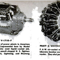
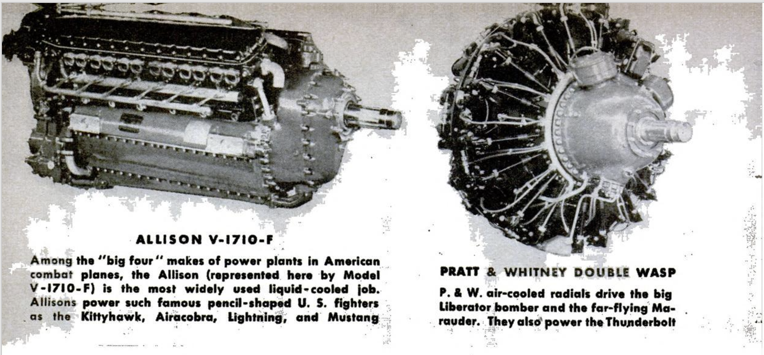
Today's miracle motors are sufficiently |
light and powerful to pull the 82-ton Doug- |
las B-19 7,750 miles at a hop (with Wright |
Cyclones), to hurtle the Lockheed Light- |
ning through the air at a speed well in ex- |
cess of 400 miles per hour (with Allisons), |
or to lift the huge Republic Thunderbolt |
into the stratosphere (with a Pratt & Whit- |
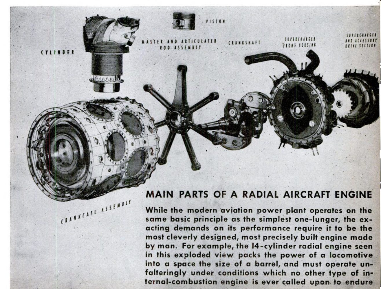
ney Double Wasp). These three basic mili- |
tary engines literally pack the power of a |
locomotive into the space of a barrel. These |
packets of horsepower are concerned only |
incidentally with sustaining the planes in |
flight; they must keep 'em flying under cer-
tain conditions or circumstances which we
refer to as “performance.”
The plane and engine designers get to- |
gether to decide how fast, how high, how far, |
and with how much load a given airplane is |
to fly in order to fulfill its tactical purpose; |
then they work out a compromise with the |
horsepower available. The packages of pow- |
er they have to work with come in a wide |
assortment of shapes and sizes differing |
principally in the number of cylinders each
type of engine has and how these cylinders
are cooled.
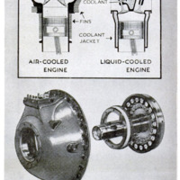
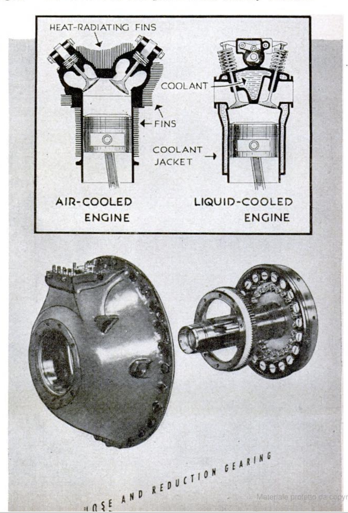
They may be exposed to the air and ringed
with a number of thin fins that serve
to increase the cooling surface, or they
may be encased in jackets containing
water or a glycol solution that is cir-
culated around the cylinders and other
working parts. In the latter case, the
liquid coolant is, in turn, exposed to
the air as it is pumped through a radi-
ator. The liquid-cooled engines which
are now in service are of the V type
and have two banks, or rows, of cyl-
inders to form the sides of the V with
the engine's crankshaft at the apex.
Other types which are gong into serv-
ice, or are in the final experimental
stages, are the W and X-shaped en-
gines. The former consists of two V
engines that are attached to each
other's sides and have a single crank-
shaft. The X engine is made up of two
V engines set opposite each other with
the crankshaft at their common apex.
The V-type air-cooled engine is com-
ing into wide use, as is also the in-
line type, having its cylinders ar-
ranged in a single row. Great things
are expected of another type of air-
cooled engine having two rows direct-
ly opposite each other and known as a
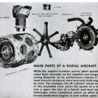
“flat-opposed” engine. But the most
popular and successful of the air-
cooled family is the radial engine,
whose cylinders are set like the spokes
of a wheel around the crankshaft.
Radials may have one, two, or three rows of
the spokelike cylinders staggered compactly.
Whatever the shape or size of the power
plants, engine manufacturers everywhere
have a three-cornered philosophy which un-
derlies their products. It's a sort of formula:
maximum horsepower/minimum weight +
maximum horsepower/minimum space
maximum horsepower/minimum fuel con-
sumption = efficient engine.
Whether air-cooled or liquid-cooled, car-
buretor type or Diesel, automobile or air-
plane power plant, the internal-combustion
engine of 1943 works on fundamentally the
same principle as the ancient steam en-
gine. In both cases heat is developed by
combustion and the heated gas or steam is
allowed to expand within a chamber which
has one movable wall. The pressure forces
this wall outward and this movement is car-
ried through various kinds of mechanical
linkage to the point where the movement
can be put to work. In an airplane engine,
the chamber where the combustion takes
place is called the cylinder; the movable wall
is the piston; the mechanical linkage con-
sists of an articulating rod, or connecting
rod, which is fastened to the engine crank-
shaft to translate the straight up-and-down
movement of the piston into rotary motion.
Let us consider what happens inside the
cylinder of an aero engine such as the
Wright Cyclone. In principle, a single cyl-
inder is an engine in itself. At the top are
two ports through which the fuel-air mix-
ture is drawn in and the burned exhaust
gases expelled; these ports are sealed by
valves that open and close in carefully timed
movements as the vaporized fuel enters and
as the gases are exhausted. The first of the
engine's cycles is the intake stroke, during
which the intake valve opens as the down-
ward movement of the piston results in a
partial vacuum and pressure from outside
forces the fuel-air mix into the upper part of
the cylinder. Next comes the compression
stroke, during which both valves remain
closed and the piston moves upward, com-
pressing the fuel into an exceedingly small
space. Just as the piston rises almost to the
top, the tightly compacted charge is ignited
by a flame from the spark plug; this results
in a very rapid burning (not an explosion)
and a consequent expansion that drives the
piston back downward. Both valves remain
closed, of course, during this power stroke.
As the piston nears its bottom maximum
and all the energy available has been gained
from the fuel combustion, the exhaust valve
opens to relieve the pressure and the piston
rises in the exhaust stroke. The exhaust
valve closes as the piston reaches its top
‘maximum, and the intake valve opens again
to permit the charge to enter the cylinder.
To develop a more steady flow of power
to the engine crankshaft, more cylinders
are added and their power strokes so timed
that the push is delivered to a single crank-
shat at different intervals. The more cyl-
inders, the more continuous the flow of
power.
The lung through which our aircraft en-
gines breathe is the carburetor, a device that
mixes the proper amount of air with the cor-
rect amount of fuel and atomizes this mix-
ture into its most combustible form—a ratio
of slightly more than 13 parts of alr to one
part of fuel. Any other ratio results in
either a rich or a lean mixture. The former
condition causes incomplete combustion and
some of the unburned fuel is drawn out
through the exhaust. The lean mix brings
about overheating.
The engine's actual purpose, that of driv-
ing the plane, is accomplished by the de-
livery of the horsepower output to the other
half of the power plant—the propeller. The
Prop screws its way through the air, pulls
the plane along, and pushes the air back-
ward in a slip stream, just as the wing gains
its lift by deflecting the air through which
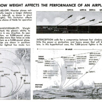
it moves. Thrust and lift give the airplane
its performance, but they must overcome
two enemies known as drag and weight. The
greater the margin by which they overcome
these, the lower is the “power loading” and
“wing loading” and the better is the air-
plane's performance. 1f two bombers are
identical in design and weight except for
their power plants, the more powerful will
be the faster, at all altitudes and under all
conditions.
Under ideal conditions, about 86 percent
of the engine's power output can be trans-
lated into useful thrust by the propeller. But
because of certain limitations in the size
and rotating speed of props, ideal—or even
favorable—conditions are difficult of achieve-
ment. Prop and engine must be carefully
mated because, for every combination of the
two, there is an optimum speed for the prop.
On the other hand, the engine's best output
is gained at a constant r.p.m., or crankshaft
speed, which usually is higher than the pro-
peller’s optimum. To make it possible for
both the engine and the propeller to turn at
their most suitable speeds, a set of reduc-
tion gears is built into the nose section of
the engine to slow down the prop to be-
tween 50 and 75 revolutions to the engine's
100.
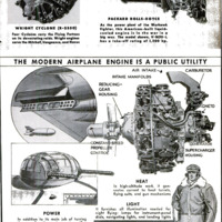
Unfortunately for the plane and engine
designers, the power plant must do
much more than provide this thrust.
The whole rear end of the engine is
encased in an accessory-section hous-
ing which, in turn, is filled with gearing
and drives for all sorts of auxiliary
equipment. First of all, the engine must
feed itself with fuel and oil.
There are one or two fuel pumps in
the accessory section whose job it is to flow
gasoline from the tanks to the carburetor
through the fuel lines at a pressure in the
neighborhood of 16 pounds per square inch.
High-powered engines drink up fuel faster
than you can pour liquid out of a milk bottle,
and this pressure must be maintained in or-
der to insure operation under all conditions
of flight.
An oil pump is mounted on the engine to
provide lubricating pressure. Oil in an air-
craft engine not only lubricates all rubbing
surfaces to reduce friction but also seals the
pistons around the cylinder walls to prevent
1oss of compression within the cylinder. The
engine-driven pump forces the ofl from the
tanks through the lines and into the oil ports
at a pressure of about 70 pounds per square
inch. The pump also scavenges run-off ofl in
the engine sump and returns it to the tank.
When a hydraulic-type propeller is used, an
additional ofl governor pump is used to sup-
ply the prop hub mechanism. After receiv-
ing its ill of food, the engine must go about
the business of digestion, and this is ac-
complished with the aid of more gadgetry in
the rear accessory group.
The ignition of the fuel mixture within
the cylinders actually starts with an engine-
driven gear that spins the magnetos and
distributors. The electric current sparks as
it Jumps between the point of the plugs and
ignites the fuel-air mixture. The move-
ments of the valves, the jumping nostrils
through which the engine breathes, are also
caused by geared cam rings (in radial en-
gines) or camshafts (in V and in-line-type
engines).
In many respects, the engine runs itself,
but it also runs just about every other mov-
ing part of the plane. The hydraulic system
that operates the landing gear, wing flaps,
bomb-bay doors, automatic pilot, gun tur-
rets and gun synchro gear, engine-cowling
cooling flaps, and other devices is furnished
pressure by an engine-driven pump. So is
the vacuum system that works various in-
struments. The electrical system, through
an engine-driven generator and dynamotor,
furnishes radio power and current for lights,
starters, and special equipment for high
altitudes (PSM, Nov. ‘41, p. 104). Liquid-
cooled engines have additional pumps to
circulate the coolant through the jackets
and radiators.
Last, but far from least, the engine ac-
cessory group has to drive the supercharger,
and it is here that most of the power drain
goes. All this extra work accounts for the
discrepancy between “indicated horsepower”
—what is actually delivered by each cylinder
—and “brake horsepower”—what is finally
delivered to the propeller to result in thrust.
Another interesting aspect of the engine's
operation deals with the conditions under
which it must power the plane and drive all
the essential accessories. Never faltering in
its pace or its even rhythm, the double-duty
airplane engine is forced to climb through
the normal air layer at sea level up to the
stratosphere where the air has only a frac-
tion of its sea-level density. In the desert
regions, a fighter might take off from a spot
having a temperature of 120 degrees F. and,
within half an hour, climb to the upper air
whose temperature would be 50 or 60 de-
grees below zero. The engine must function
as well while lying on its side as the fighter
screws around in a vertical turn as it does in
smooth, level flight; it must be equally re-
liable while standing on its nose in a power
dive and while lying on its back in a ver-
tical zoom. These are conditions under
which no other kind of internal-combustion
engine is forced to operate, or could oper-
ate. For this reason, the airplane engine
must be more cleverly designed, more care-
fully assembled and maintained, and built of
better materials, than any other type of
power plant.
Here is an example of the sort of precision
work which makes for this high standard of
performance. Mention was made of the re-
duction gear in the engine's nose that per-
mits engine and propeller to act with better
teamwork. A key unit in this set of plane-
tary gears is a set of 20 small pinion gears
that, in a Wright Cyclone, connect directly
to the prop shaft. A single tooth of one of
these pinions has a face with an area small-
er than a thumbnail but, with each contact
against an adjoining gear tooth, this tiny
area transmits 1/20 of the total horsepower
output. The gears in the accessory drive
turn at terrific speeds—some at almost 10
times crankshaft speed—but they are
worked to tolerances ranging from two to
three ten-thousandths of an inch. An error
as small as .0005 inch, as compared with
.0002, can almost double the stresses on a
single tooth of a gear. A discrepancy no
greater than this can result in the loss of
between 10 and 15 horsepower. The small
est engines in military service, such as the
Lycomings or Continentals or Franklins
that power the Army's grasshopper light-
planes, are built to closer tolerances than
the finest auto engine. In Wright and Pratt
& Whitney engines which develop 2,000
horsepower or better, parts must be ground
and polished with even greater precision.
An’ automobile engine is broken in by
easy running for several hundred miles,
simply because the parts are not so care-
fully ground and must wear themselves into
proper lap through friction. This type of
engine rarely, If ever, develops its full horse-
power. The aircraft engine commences its
life, during the very first take-off, at full
power and is run at full throttle at some
time or other in every flight.
Under all these conditions, the aero en-
gine is influenced in its operation by its
teammates, the propeller and supercharger.
The latter should be considered not as an
auxiliary, but as an actual part of the power
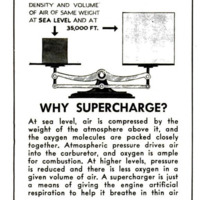
plant. Almost all military engines are super-
charged, because the power output varies
in direct proportion to the amount of air
supplied to the cylinders. At sea level, at-
mospheric pressure enables the fuel-air mix-
ture to enter the cylinder during the intake
stroke. As the plane climbs higher, however,
the density of the air diminishes and the
pressure becomes insufficient to push the re-
quired amount of
air into the cylinder. Combustion occurs
only in the presence of oxygen, and this vital
gas becomes scarce at high altitudes because
the oxygen molecules are widely scattered.
At sea level, the molecules are compacted by
the mass weight of all the air above. It is
the supercharger’s function to suck in as
many oxygen molecules as possible, cram
them into the carburetor, and deliver this
compressed air-and-fuel charge to the cyl-
inders.
‘The most widely used type is the centrif-
ugal supercharger which consists princi.
pally of a many-bladed fan or blower, called
the impeller, that is driven at high speed by
a train of gears linked with the engine
crankshaft. Centered within a housing at
the rear of the engine, the impeller whips
the atomized fuel against a unit resembling
a pinwheel, known as the diffuser. Unlike a
pinwheel, however, the diffuser doesn't turn;
its function is to slow down the terrific ve.
locity of the vapor as it comes off the im-
peller-blade tips, changing the speed to
pressure. The supercharger does something
besides boost the mixture intake: the whirl:
ing blades of the impeller agitate the fuel
and air into such turbulence that a much
higher degree of vaporization is gained—
the oxygen molecules are more evenly mixed
with the particles of gasoline and more com-
plete combustion results. Furthermore, this
turbulence hastens the transfer of heat after
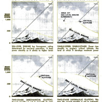
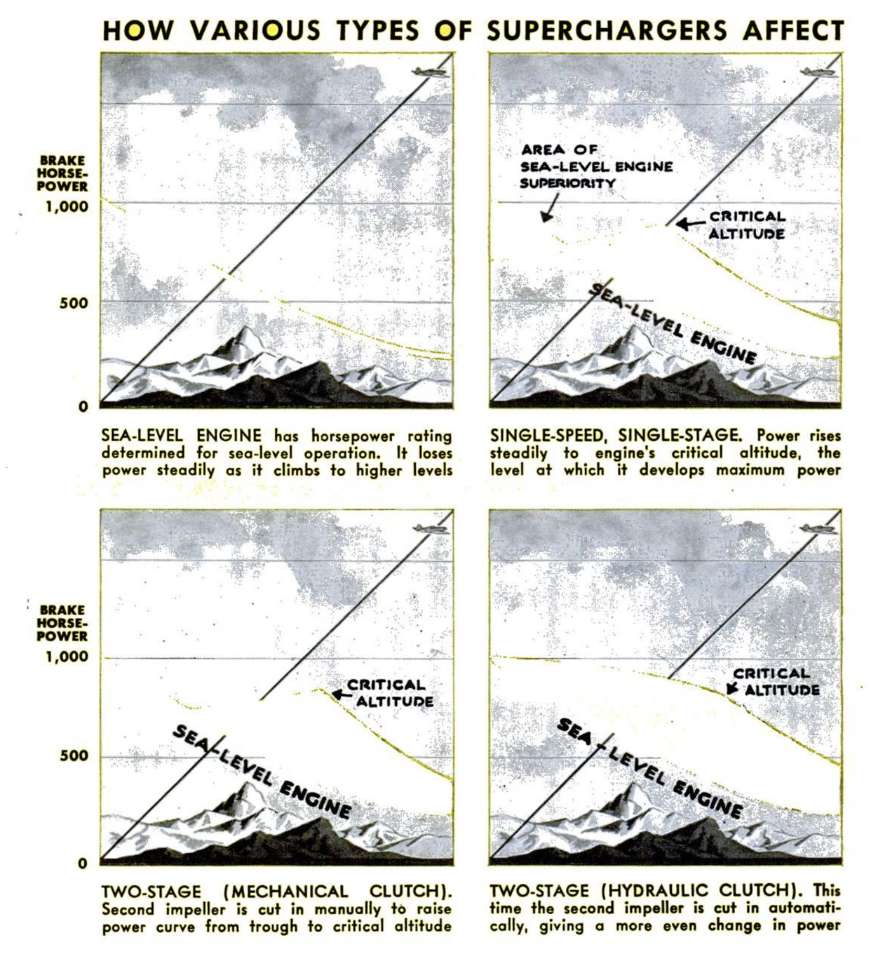
the power stroke. This variety of super-
charger, having one impeller that turns at
constant speed, say, seven times the crank-
shaft r.p.m., is called a “single-stage, single-
speed” supercharger.
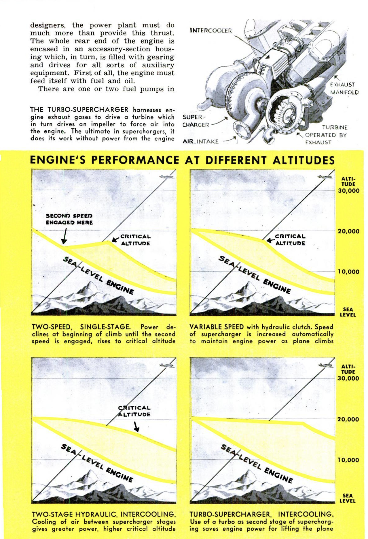
When the impeller is geared in low and
high ratios, the super is called a “single-
stage, two-speed” type. After the manner of
the low and high gears in an auto, the
former is used for the take-off and ascent to
intermediate levels and then stepped up to
high ratio for the long climb to higher alti-
tudes. The change-over is made through a
mechanical clutch which is operated by the
pilot, or may be made gradually with a
semiautomatic hydraulic clutch that oper-
ates on the fluid-drive principle.
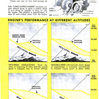
In the higher horsepower brackets, we
find the “two-stage” supercharger, having
two impellers connected in a series. The
first stage of compression is routed on to the
second blower for additional boosting before
being fed to the cylinders. This impeller
may be cut in manually by a mechanical
clutch, or automatically by means of a
hydraulic clutch. Intercooling, a radiator
system for lowering the temperature of the
highly compressed mixture as it passes from
one stage to the other, is sometimes used be-
tween the two impellers to prevent pre-
ignition or detonation in the cylinder.
The ultimate in superchargers is the tur-
bo-blower. This type is used in combination
with a built-in_single-stage “super” and
usually is installed on the outside of the
engine cowling. The motor’s exhaust is dis-
charged at pressures considerably higher
than those of the atmosphere, and the turbo
utilizes these gases which would otherwise
be wasted. Furthermore, it makes use of
this power without robbing the engine: the
centrifugal types eat up as much as 200
horsepower—enough to fly another good-
sized airplane. The exhaust is routed
through a small turbine that turns an im-
peller mounted on the same shaft, and this
boost is passed on to the engine intake.
Installations in our most famous war-
planes include all these methods of super-
charging. The Bell Airacobra models which
have been in service for some time are
powered by an Allison liquid-cooled engine
that uses a single-stage, single-speed super- |
charger. The Lockheed Lightning's two Al- |
lisons have their single-stage supers com-
plemented by General. Electric turbo-super-
chargers (P.S.M. June '41, p. 66). The
high-flying Boeing Flying Fortress is pow- |
ered by Wright Cyclones that use both |
single-stage and turbo-supercharging. The |
Republic Thunderbolt has a turbo-super con-
nected with its Pratt & Whitney Double
Wasp engine. The Vought-Sikorsky Corsair
uses a Double Wasp with two-stage two- |
speed supercharging. Three-stage super-
chargers—a built-in, two-stage blower sup- |
plemented by a turbo—are now in the works.
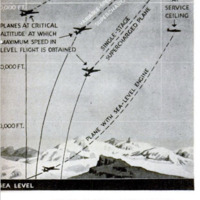
Retaining the engine's sea-level power at |
high altitudes is only part of the conquest
of the stratosphere. Controllable propellers
whose blades may be changed in their pitch, |
automatically or manually, are essential be-
cause of the need for the propellers to get a
bigger bite on the rarefied air of the upper
levels. For take-off and initial climb, the |
blades are set in low pitch, so that they |
appear flat and thin when viewed from the |
side. In this position, the blades have little |
braking effect on the engine, permitting it
to revv up to full power for maximum pull.
In high pitch, the blades meet the air at a
greater angle and thus maintain thrust in
thinner air; they also prevent the engine
from racing and losing efficiency. In hydro-
matic or electrically controlled propellers,
the blade angle is changed automatically
during the climb to permit the engine to
operate at its best rpm. reading.
The amount of boost being furnished to
the intake by the supercharger is indicated
to the pilot on a manifold-pressure gauge
that is calibrated in “inches of mercury,”
and he tells how fast the engine is turning
over by watching the indicated r.p.m. on the
tachometer. Different engines, and differ-
ent models of the same engine, are rated ac-
cording to their optimum output under cer-
tain combinations of manifold pressure and
rpm, regardless of whether they are sea-
level engines or altitude engines. For ex-
ample, a boost of 35 inches and a reading of
1,900 rpm. is maintained as the plane
climbs by opening the throttle gradually.
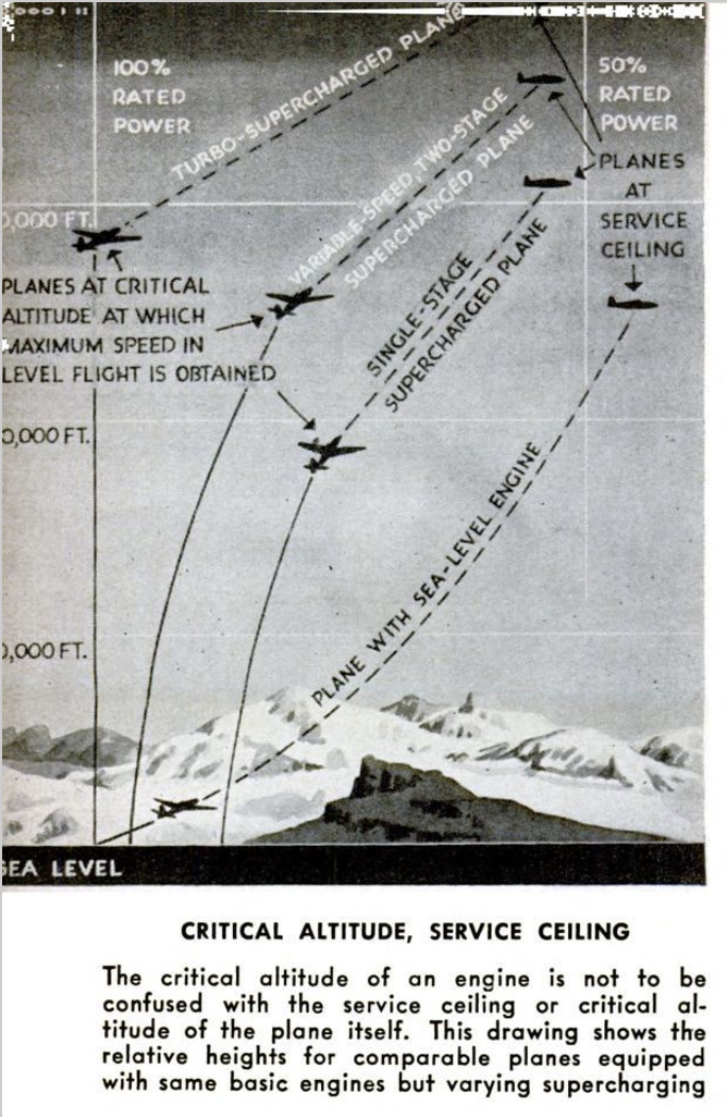
When the altitude is reached where you can
maintain these readings only at full throt-
tle, you have reached the “critical altitude”
of the engine—the level at which it develops
its maximum power output. This is not to
be confused with the critical altitude or
service ceiling of the plane itself, which is
many thousands of feet higher. Engineers
are striving toward the goal of getting the
critical altitudes of engine and plane as
close together as possible.
Another objective is to decrease the horse-
power-welght ratio of their engines, and re-
markable advances have been made in this
direction. This is one of the points of marked
superiority of American engines over those
of the European nations. The first Wright
engine weighed 12 pounds per horsepower.
Until about three years ago, the one-
pound/horsepower ratio was considered the
ideal, but now we have surpassed even this
standard.
But lower horsepower-weight ratios will
be achieved in comparatively small measure
by making the engines themselves lighter.
The problem is being attacked from another
angle, that of increasing the horsepower by
a greater percentage than the engine's
weight, The new engines are considerably
heavier, but they are so much more power-
ful that the horsepower-weight ratio is
lower.
The efficiency of our power plants de-
pends upon packing more horsepower into a
package which is relatively the same weight
and size. This is being accomplished by the
use of forged cylinder heads, better cooling
methods, more efficient supercharging, and
use of new and lighter materials. The
Wright people lighten a Cyclone by making.
180 pounds of magnesium do the work of
270 pounds of processed aluminum. Push-
rod housings and cylinder baffles are now
being made of plastic instead of metal. The
new higher-octane fuels are doing as much
to reduce the weight-horsepower ratio as
any other single factor, because they pro-
vide more power at full throttle (both at
take-off and at critical altitude) increase
the engine's critical altitude, and bring
about lower fuel consumption.
Superb as our engines now are, even finer
ones are going into service in the near fu-
ture. They are designed for mass produc-
tion and easy field maintenance. However
efficient an engine may be, it is not a good
military power plant if it cannot be pro-
duced in sufficient quantity to get the re-
quired number of planes using this engine
into tactical service. Nor is it good if it is
s0 complicated in design that mechanics—
who may have to work in the desert or in the
Arctic, and with only limited equipment—
cannot keep it in service. This is another
department in which U. S. engines excel;
they run well, do not require too frequent
overhaul, and are easy to service.
Rather than new ideas, it seems likely
that we shall see, in late war engines and
the engines which will power our peaceful
wings, new applications of older basic prin-
ciples. Fuel-injection power plants, reac-
tion-type engines, and perhaps jet propulsion
may come into wider use, but it is doubtful
if any of these will replace our present war
engines. The conventional types are too
good, and we shall have a lot of them.
-
Contributor (Dublin Core)
-
James L. H. Peck (writer)
-
Language (Dublin Core)
-
eng
-
Date Issued (Dublin Core)
-
1943-06
-
pages (Bibliographic Ontology)
-
108-115, 204, 206, 208, 210
-
Rights (Dublin Core)
-
Public Domain (Google digitized)
-
Archived by (Dublin Core)
-
Matteo Ridolfi
-
Alberto Bordignon (Supervisor)


 Popular Science Monthly, v. 142, n. 6, 1943