-
Title (Dublin Core)
-
The range-finders used in the army
-
Article Title and/or Image Caption (Dublin Core)
-
Title: Range-Finding in the Army
-
Subtitle: How to use range-finders to get result: the erect and inverted types
-
extracted text (Extract Text)
-
THE ability to estimate distances,
or find the range correctly, is
a very important part of a
soldier's education. Fire on the battle-
field is usually by groups of men, and
the range is given by the officers; but
the battlefield is reached only after a
great deal of scouting, patroling, and
outpost duty, in which the soldier
‘must depend upon his own powers of
estimating dis-
tances in order to
make his fire effec
tive.
There are several
ways of estimating
distances. There
are sound, trial
shots, field-glasses,
range-finding in-
struments, ete.; but
the only onea
soldier can depend upon is his ‘eye and
occasional trial shots. To estimate
the range with the eye, it is necessary
to be familiar with the appearance of
a given unit of length, say 100 yards,
and this is obtained by practising with
different distances and then measuring
them. The estimate may also be
checked by noticing the appearance
of the uniform, its clearness, the move-
ments of the men, and other little fea-
tures that will help him to solve this
problem. Field silhouettes are also
good practice, since they represent—
to a certain extent, at least—conditions
under which estimating will have to be
done when actually in battle.
Some Obstacles to Range-Finding
Trial shots and ranging volleys are
practicable when the earth is dry
enough for the bullet to kick up some
dirt when it strikes, the usual prac-
tice being to fire the first shot or volley
at an estimated range, and then to
increase or decrease the elevation of
the piece until the bullets are falling
in the desired place. There are many
conditions that will bother even expert
estimators.
Objects will appear to be nearer when
they are in a bright light; when the
color of the object contrasts with the
color of thebackground; when thesoldier
looks over water, snow, or a uniform
surface, such as a field of wheat or
oats; when looking from a height
downward; when in the clear atmos-
phere of high altitudes.
Objects will appear at greater dis-
tances when looking over a depression
in the ground; when there is a poor
light or a fog; when only a small part
of the object can be seen; when looking
from low ground upward toward higher
ground.
It will be seen, therefore, that it is
really difficult for any one man to
get the range with even a fair degree
of accuracy, unless the conditions are
just right.” It is therefore customary,
When any number of men are shooting
together, for the officer in charge to
pick out from four to six men and have
each one estimate the range of the
target, the average of the estimates
being taken as the correct range, until
some line may be obtained on the
actual distance. This method is fair
enough; but the use of instruments,
when they are obtainable, is much
more reliable.
Mechanical Finders
Mechanical range-finders are known
as erect-image and invert-image types
of coincidence
range-finders.
The erect image
type is generally
used for naval
and coast defense
purposes where
the objects have
well defined out-
lines such as
smokestacks,
flag-stafls, and
the like, which
permit of precise alignment of- the
image.
The invert-image range-finders dif-
fer from the erect-image finders in
that the image appearing in the upper
half of the field is an inverted image of
the lower half, but is not reversed right
or left. The view through the eye-
piece of this type of range-finder, when
properly adjusted, is shown in Fig. 1.
The instrument must be held steady,
since a slight elevation will cause the
image to separate vertically from the
halving line, making it difficult to
effect a coincidence.
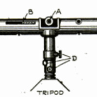
The army type of invert-image
rangefinder is shown in Fig. 2, in
which A is the eye-piece, B the scale
showing the exact number of yards
to the object sighted, C the halving ad-
justment, and D the leveling screws.
These instruments are very compli-
cated in their construction, and must
be frequently checked against a known
distance or corrected with the aid of
an adjusting lathe which is part of
the equipment of each machine. Each
instrument is also provided with a
two shade ray filter, smoked for ob-
serving the rays of a searchlight,
and amber to moderate exceptionally
bright daylight, either one being
brought into use by turning a small
lever on the eye-piece housing.
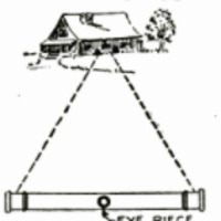
The rangefinder, by means of a
series of prisms, merely determines
the triangle; and the longer the base
of the instrument the more accurate
the measurements. The theory of the
method of obtaining results with this
instrument is shown in Fig. 3. When
properly adjusted the image in the
eye piece would be, in this case, as
shown in Fig. 1.
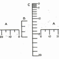
Scale on Army Glasses
The quickest and most common way
of determining ranges, except by using
the average of several guesses, is by
means of the range estimating and
corrector scales engraved on the left
lens of army field-glasses. These
scales are shown in Fig. 4. The
scales marked A-A in the drawing are
known as the mil scales; B as the
vertical mil scale; and C as the range
corrector scale. The mil scales are
used to determine the range, and the
corrector scale to correct it.
To determine the range by the use
of the scale, one must first estimate
the width or height of the object
sighted and then figure the range by
the formula: Range equals width or
height x 1000 mils.
For example: In Fig. 5 let it be
considered that.
the buildingsighted
is 80 ft. wide. This;
is estimated more!
or less accurately
by the number and
width of the win-
dows, doors, ete.
By holding the!
horizontal mil scale upon the object, we
find that the building cuts off 25 mils,
0 that our range becomes
In Fig. 6 we are using the average
height of the telephone-poles in a
certain vicinity which is about 20 ft.
By focusing the vertical scale (mil) on
the pole, wefind that it is just 20 mils
high; therefore our range is
It is a comparatively easy matter
to judge the width of buildings and
other objects of like
nature, if attention |
is paid to the style
of building used in |
a certain locality, |
the width of doors,
windows, and aver-
age height from
the ground to the
cornice. etc.
The use of the range corrector scale
is shown in Figs. 7 and 8. In Fig. 7the
enemy is in a clump of bushes 1000
yards distant from us, We can see
them with our glasses, but the men on -
the firing line cannot see them with
the naked eye. In order to make
their fire effective we must give them an
auxiliary aiming point, and we accom-
plish this by placing the 1000 mark,
10 on the scale, on the enemy position,
and find that the line of hills in the
background cuts the scale at 500
yards. Therefore the men set their
sights at 500
yards instead of
the 1000 yards,
and aim at the
ridge of the hills
instead of the
clump of bushes
in which the
enemy is hiding.
The result is that
the bullets drop
into the enemy
position, and with
just as good an
effect as if they
were fired from
a point where the
target could be clearly seen.
In Fig. 8 we have a concealed trench
1100 yards distant from us; but, be-
cause of its concealment, it cannot be
picked out with thé naked eye. We
therefore place the 1100 mark of the
corrector scale on
the enemy position,
and look for a well
defined auxiliary
aiming point.
There is no distinct
point in the rear of
the trench, but
there is a fence in
the foreground
which all of the men
can seeclearly. This
fence cuts the scale
at 1400 yards, so
that the men lift
their sights to 1400
yards elevation anc aim at the top of ;
the fence, the bullets dropping into |
the trench 1100 yards away.
Although the field-glass method of |
estimating ranges is not so accurate as
is the range-finder method, because of
the fact that the width or height of the |
object must be determined before-
hand, it is nevertheless a fairly ac-
curate’and a very’ handy method to
use in an attack where ranges must be
quickly determined. In long-range
firing it is not necessary to aim at
a particular individual every time a
shot is fired, since ‘by keeping the
bullets dropping thickly around an
enemy position they will become more
or less demoralized and will not return
a heavy fire.
How to Conquer the Stubbornest
. Jar Top
I= frequently happens that the screw
cap on a jar or bottle becomes stuck
so that it is almost impossible to un-
screw it. A simple method that will
bring the most stubborn cap to instant
subjection is shown in the illustration.
Cut a piece of sandpaper into a long,
narrow strip about twice the width of
the cap to be removed, and fold it so
that there" will be a sand surface on
both sides. Place this around the cap,
and then wind a piece of stout cord—
not string—around the sandpaper,
crossing the second round over the
first to prevent slipping. Two or three
turns of the cord will be sufficient.
Now tie a loop in the end, slip a poker
or a piece of broomstick through it,
and apply pressure. The tightest
cap must come off, provided you use
cord that is heaVy enough to stand
the strain. —ALBERT E. JONES.
How to Use Old Inner Tubes
of Automobiles
To these times when, the price of
tubes has so materially increased
the cost of running an automobile, it
behooves us to see that they give the
greatest possible service. Do not
throw away old tubes. Cut them up
and use them in every way your in-
genuity may suggest.”
Washers, silencers for chair legs.
rubber mats, and insulation for elec-
trical instruments may be made from
them. Small pieces of tubing placed
under glass table-tops will prevent
scratching of the table and make it
easier to move the glass. A long strip
may be cut from an old tube and used.
to prevent the rattling of an automo-
bile wind-shield, a frequent source of
annoyance, while similar strips can be
used advantageously for weather-strip-
ping on windows and doors.
These are only a few of the possible
uses to which old tubes may be put.
-
Contributor (Dublin Core)
-
George M. Petersen (Article writer)
-
Language (Dublin Core)
-
eng
-
Date Issued (Dublin Core)
-
1919-02
-
pages (Bibliographic Ontology)
-
118-120
-
Rights (Dublin Core)
-
Public domain (Google digitized)
-
Archived by (Dublin Core)
-
Davide Donà
-
Marco Bortolami (editor)


 Popular Science Monthly, v. 94, n. 2, 1919