-
Title (Dublin Core)
-
The Army Air Forces laboratory tests newly developed airscrews
-
Article Title and/or Image Caption (Dublin Core)
-
Title: Proving ground for props
-
Subtitle: Newly designed airscrews undergo grueling tests at Wright Field, where delicate instruments show how they will withstand strains encountered in actual flying
-
extracted text (Extract Text)
-
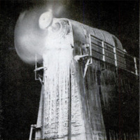
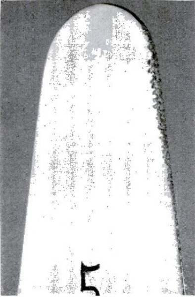
HOW will a propeller blade of new de-
sign behave when it whirls at full
speed through the air? Tiny oblong strips
of carbon, attached along its length, help
answer the important military question in
the great propeller-testing laboratory of the
Army Air Forces at Wright Field, Dayton,
Ohio. The laboratory has been designed and
built by, and is operated under direct charge
of, D. Adam Dickey, a civilian electrical
engineer, who has been cited for exceptional
performance by the Secretary of War.
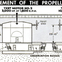
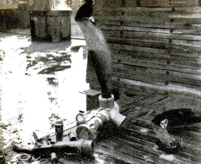
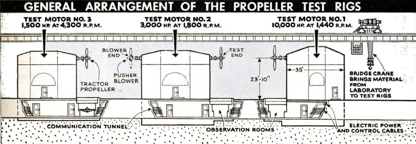
Spun by electric motors ranging in speed
up to 4,300 r.p.m. and in power up to 10,000
horsepower, propellers as large as 16 feet
or more in overall diameter give up their
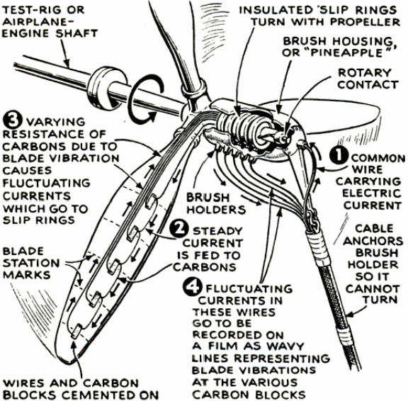
secrets. Bending and twisting, the blades
impart their strains to the telltale thin
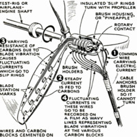
carbon strips. And these, in turn, “telephone”
their report in the form of fluctuating elec-
tric current, just as do the carbon granules
in a telephone transmitter. The pulses cor-
respond to changes in the electrical re-
sistance of the carbon, according to the
degree of pressure upon it. On the propeller
blade, individual wire circuits lead from each
carbon strip down along the blade base and
hub to a fixed collector known from its
shape as a “pineapple.”
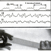
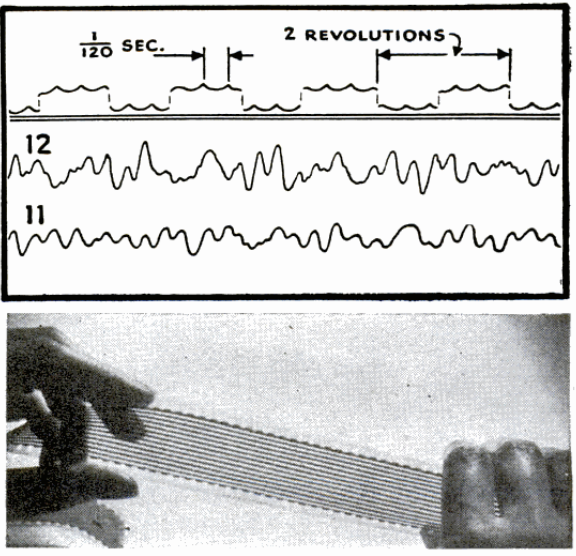
Much as sound traces are imprinted upon
motion pictures, current channels from the
collector simultaneously trace 12 parallel
lines on 35-mm. movie film. Upon develop-
ment, each vibration record is seen to be
an irregular wavy trace. Like the sound
trace of a symphony orchestra, it combines
‘many different vibrations. These may come
from the blade itself, its mounting, or its
gearing, and may include harmonic tones—
such as those heard from a musical. instru-
ment in addition to its fundamental pitch.
If gasoline engines are substituted forselec-
tric power, vibrations from cylinder ex-
plosions also enter into the record.
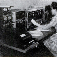
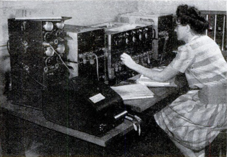
To unscramble this medley, the test film is
“played back” in a sound-analyzing room.
For audience, it has no human ears. In-
stead, a photoelectric-cell pickup silently
transmits impulses to an electrical analyzer,
a marvel of science believed to have no
counterpart in the world. Here the complex
vibration is broken down into its com-
ponents. Not only may an observer view
the results in glowing lines on the windows
of cathode-ray tubes, but a permanent
record also is made upon sensitized paper.
Thus the vibrations most important to re-
duce are traced to their source and corrected.
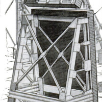
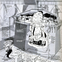
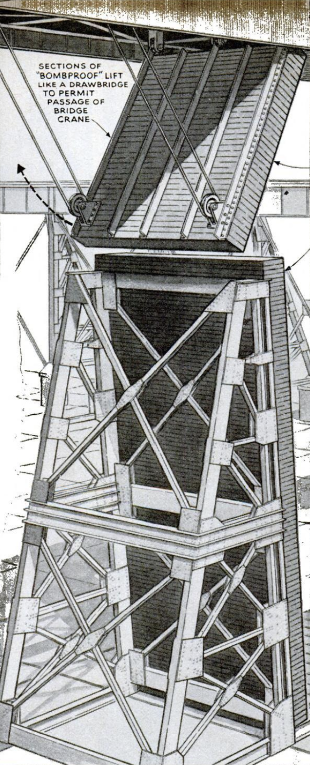
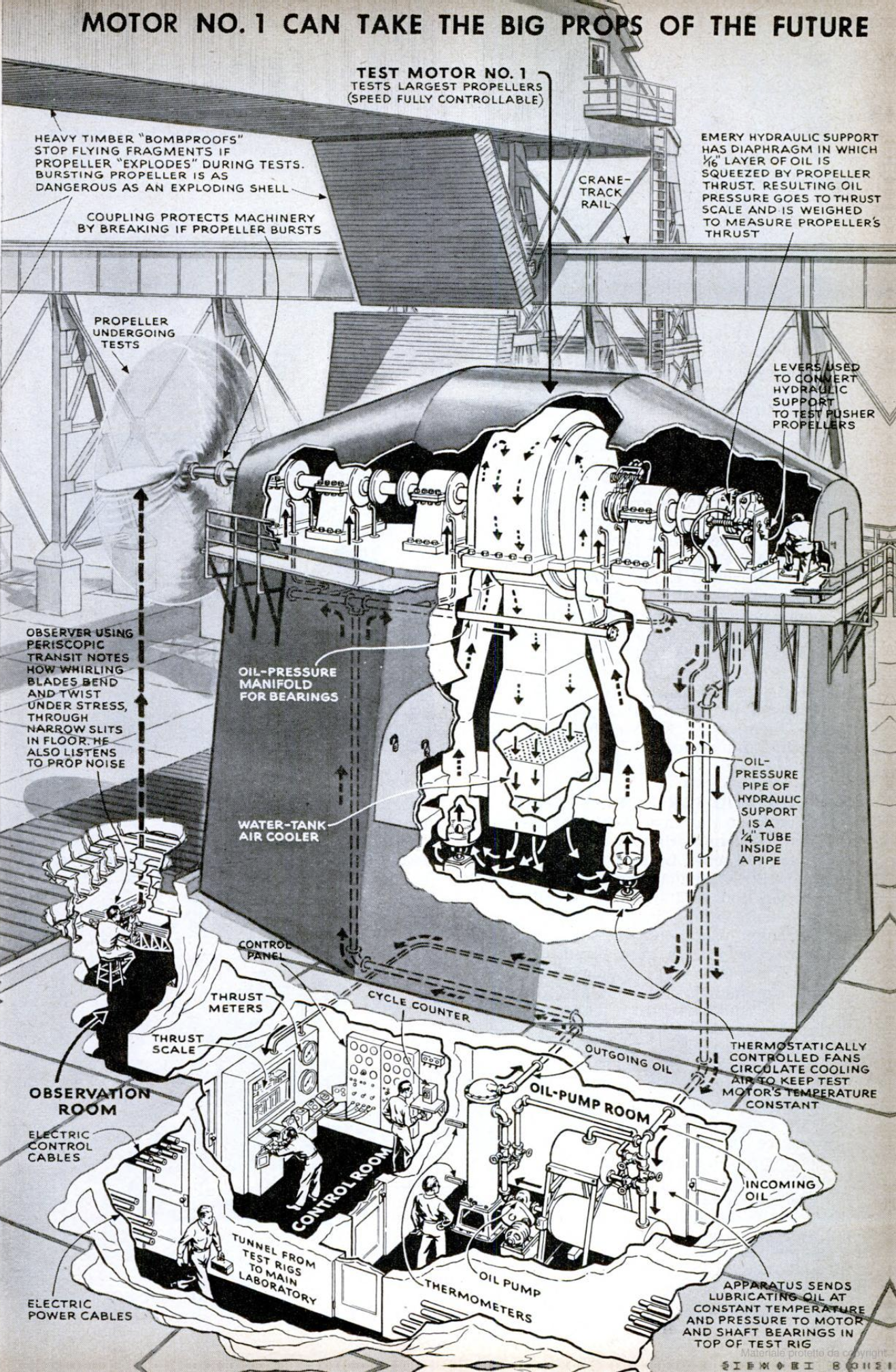
Safe in a tunnel roofed with steel I-beams
and heavy timbers, another observer watches
the propeller during the test, using a transit
as a periscope to sight through a slit in his
protective covering. Many a pilot would be
surprised, if not alarmed, to see blades that
he thought were rigid become flexible and
bend from their standstill
position. Actually this is per-
fectly normal. To find just
how much a propeller can
stand, it may be tested to
destruction, by running it at
much higher speed and load
than will ever be needed in
service. Since flying pieces
are thrown off in the plane of
the circular path of the pro-
peller, the safety walls may
be of very moderate width.
Once the breaking point is
found, engineers assure the
pilot a generous margin of
safety.
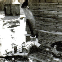
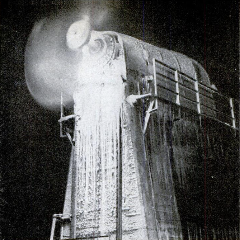
Behavior of a propeller in
rain, which nicks its leading
edges, and in icing weather,
which alters its curvature,
shows up in special tests.
How much pull or push a
propeller exerts — engineers
call it thrust—naturally is a
paramount consideration.
While electric meters meas-
ure the power delivered to the
motor, and a counter records revolutions
per minute, the propeller shaft bears
upon an Emery hydraulic cell through a
Kingsbury thrust bearing so that the
thrust is ultimately indicated by means
of a dial or weighed on a sensitive balance.
The three electric test stands of the
installation have been designed for both
present and future needs. An airship
propeller as large as 40 feet in diameter
could be tried out. And, despite the mighty
forces at play, precision governs.
When manufacturers submit competi-
tive models to suit new Government
specifications, the interests of the Air
Forces and fairness to the makers both
demand that the propellers must be
tested under precisely the same condi-
tions. Hence an elaborate system of
ventilating and lubricating, in each test
stand, maintains constant motor and oil
temperatures, with unvarying oil pres-
sure in the bearings throughout com-
parative trials. Allied airmen thus are
sure of getting the best that our fac-
tories know how to produce.—ALDEN P.
ARMAGNAC,
-
Contributor (Dublin Core)
-
Alden P. Armagnac (article writer)
-
Stewart Rouse (illustrator)
-
Language (Dublin Core)
-
eng
-
Date Issued (Dublin Core)
-
1944-04
-
pages (Bibliographic Ontology)
-
66-69
-
Rights (Dublin Core)
-
Public Domain (Google digitized)
-
Archived by (Dublin Core)
-
Lorenzo Chinellato
-
Marco Bortolami (editor)

 Popular Science Monthly, v. 144, n. 4, 1944