-
Titolo
-
A History of Landing-gear design
-
Article Title and/or Image Caption
-
Can we land our planes safely? As our war birds gain in speed and weight, the gear that gets them off the ground has to take a terrific beating
-
extracted text
-
NOT long ago, a mammoth new experi-
mental bomber was trundled out of its
concrete-floored hangar onto the macadam
apron in front of the building—and prompt-
ly sank into the surface up to its hubs! The
weight carried by its giant wheels was too
much for paving designed to support the
heaviest aircraft previously built. After the
plane was fished out, those wheels not only
carried it safely to a take-off, but even were
fully retracted in flight!
A Flying Fortress smashes down upon a
runway in an emergency landing, not with
its normal dead weight of 30 tons, but with
60, 80, or even 90 tons of impact weight. The
landing gear takes it, and can take it again
and again if need be.
Fighter pilots get the word of enemy air-
craft approaching and rush to their planes
waiting with the engines roaring. They hur-
tle down the runway and take the air. The
landing gear retracts into the fuselage and
wings and becomes invisible—in 20 seconds!
Upon their return, this same gear drops and
‘becomes locked in landing position in 15 sec-
onds. Moreover, the pilot knows at a glance
at his instrument board exactly what posi-
tion his landing gear is in at all times.
These are examples of the accomplish-
ments of the engineers and designers of
landing gear for our modern aircraft; ac-
complishments in the face of the most rigid
space and weight limitations, for once the
plane is airborne, landing gear becomes a
liability rather than an asset.
There has always seemed to be a good-
natured battle between the aircraft and
landing-gear designers —to see which could
EYP the other out of more space, but some-
how or other they always get together in
the end. Neither can succeed without the
help of the other.
The problem confronting the gear design-
ers varies with the ship itself, its mission, its
speed, and pilot who will fly it. Training
ships require sturdy gear and wide tracks
(space between the wheels) for the ragged
landings of students. Bombers need plenty
of track, too, coupled with extreme weight-
sustaining qualities and equipment to re-
tract the heavy gear. Fighter planes must
be equipped with gear that can be retracted
and locked in 20 seconds and lowered and
locked in 15 seconds, brakes for short stops
on small fields, and rugged tires that can
stand high-speed landings on rough fields.
As the weight and speed of modern aircraft
increase, the designers of landing gear must
provide safe, reliable, and compact landing
gear to keep pace with them.
Tire engineers must, in turn, keep up with
the gear designs and provide tires to with-
stand the tremendous loads, impacts, and
burns encountered in hundreds of landings
on the worst possible runways. Tires can
be made only so big, for there is limited
room within the ships to accommodate them.
To see just what this means in really big
ships, consider the B-19, the Army's huge ex-
perimental bomber, with a span of 212 feet
and a weight of 60 tons loaded. The single
tires of this giant are eight feet in diameter
and weigh over a ton apiece, with the wheel.
Yet failure to retract them entirely would
cut several hundreds of miles off the range
of the monster plane, which is 7,750 miles.
Speed, too, must be considered in these
giants, but in fighter planes the factor of
speed is of even greater importance than
strength in the design of retracting gear.
The Army Air Forces do not install re-
tracting gear on aircraft having speeds less
than 175 mph. except in special types of
trainers designed to acquaint students with
its use. Above the 175-m.p.h. class it is al-
most mandatory, for its advantages far off-
set the added weight. (Equipping a plane
with retracting gear calls for about 15
pounds of reinforcement for every pound
of the gear and its retracting equipment.)
With the present aircraft engines, speeds of
over 300 m.p.h. would be next to impossible
with fixed landing gear.
Naturally, these higher speeds mean that
the landing speeds will be proportionately
greater, and the gear must be designed to
take the impact safely time and again on
any surface. The fact that the surface of
the landing area is not always of the best,
and often far from it, has brought new pop-
ularity to an old idea—the tricycle landing
gear. Such combat aircraft as the Bell P-39
and the Lockheed P-38, as well as the giant
Consolidated B-24 and the Douglas C-54, use
the tricycle gear. So do the medium bomb-
ers in the North American B-25 and Martin
B-26 class.
The admitted safety of the tricycle gear,
ease of ground handling, and better visibil-
ity indicate that this type of gear will soon
be standard on private and commercial as
well as military aircraft.
One of the greatest advantages of this
gear is the ability of the craft to operate
from much smaller fields. The pilot may
safely apply his brakes almost as soon as he
“tduches down,” and in the take-off he need
not use up valuable runway in getting his
tail up into flying position, for it already is
elevated before the take-off run is started.
The inclusion of tricycle gear of either
retracting or fixed type will undoubtedly be
mandatory in future private planes, because
of its obvious safety advantages. At pres-
ent, such ships as the Skyfarer and Ercoupe
already feature it.
As we trace the history of landing gear
from the time when Lilienthal used his run-
ning feet for glider take-off, we find many
novel ideas in gear design. The first me-
chanical landing gear is claimed for the
“Eole,” built and said to have been flown in
1890 by Clement F. Ader, of France. This
weird aircraft landed, though tragically, on
three ski-like skids on the bottom of the fuse-
lage, similar to those later used on the
Wright airplane.
Strangely enough, wheels—now accepted as
standard landing gear for all but seaplanes
—were employed on an experimental air-
craft long before the skid-equipped Wright
plane actually flew.
In 1803, Horatio Phillips, an Englishman,
built a tethered aircraft that rested on a
tricycle gear. This machine ran around a
circular track and at 40 miles an hour took
off and circled the track several times.
Wheels, of course, rapidly became stand-
ard equipment and appeared in various sizes
and types. At first they were rigidly at-
tached to the struts, but the impact of land-
ings broke rims, spokes, tires, and struts,
indicating that some sort of shock-absorb-
ing device was needed. One of the first air-
craft to employ steel springs was the French
Voisin, made famous by Henri Farman.
France, where wheel-equipped landing gear
originated, produced many startling types of
gear. One featured tandem wheels on the fu-
selage and a wheel attached to each wing tip.
Enclosed wheels, common during World
War I, appeared in 1908. Records show that
a small triplane, built by the Danish fiyer
Ellenhammer and powered with one of the
first tractor propellers, featured a tail wheel
closed in with fabric. This evidently was in-
tended to serve as added fin area for stability
—which most pioneer aircraft sadly lacked.
World War I saw general acceptance of
the enclosed wheel, elastic shock cords, and
also the strut-and-spreader-bar design. The
closed-in wheels increased the speed slight-
ly, the elastic cord was adequate for shock
absorbing, and the spreader bar added
strength.
As speed became more important, the
drag of rigid landing struts presented a dif-
ficult problem. Anthony Fokker made an
important contribution in his famous Fok-
ker D-T and subsequent models by design-
ing the spreader bar as a high-lift airfoil
section between the wheels.
Various types of streamlined housing for
the gear were designed as early as 1912.
The Antoinette monoplane that featured
“trousers” also boasted another innovation
in a tapered cantilever wing. Farly landing-
gear “pants,” while they increased the speed
of the planes, had
their drawbacks. They usually weighed so
much that the horsepower required to lift
them was often more than that originally
required to overcome the drag of the gear
without them.
Modern design, with the help of light
metals, has produced some really satisfac-
tory “pants” for certain types of aircraft in
which retracting gear is impractical.
In 1917, the name of Capt. James V. Mar-
tin first became prominent in connection
with landing gear, when he developed a
unique semiretracting gear for his little
KIII Scout biplane, built at Elyria, Ohio.
‘This rigid-strut gear had wheels with flat
springs for spokes, which acted as shock
absorbers. By means of a crank, the land-
ing gear could be fully extended or almost
completely retracted into wells along the
side of the fuselage.
The following year, Captain Martin
brought out another innovation. On an old
De Havilland biplane he worked out the first
split-axle landing gear, doing away with the
spreader bar, which had long been a hazard
on rough fields and in tall grass.
Also in 1920 there appeared the first real-
ly retractable landing gear. A Martin de-
sign, this was fitted to the Dayton-Wright
Gordon Bennett racer for the Army Air
Corps. By means of a nut working on a
threaded shaft, and a bicycle chain, the pi-
lot cranked the wheels up and down by
hand. This ship was the forerunner of such
planes as the Grumman FF-1, delivered in
1931, the first military aircraft equipped
with retracting gear.
Boeing pioneered in hydraulic landing
gear for big stuff in 1930, fitting it to one
of their Monomail models. To test its effi-
ciency, they raced it against another Mono-
mail, which had fixed gear with the best
“pants” then available. The Monomail with
gear retracted left the sister ship far be-
hind, with a speed difference of 15 miles an
hour. Retracting gear for big aircraft was
here to stay.
Modern retracting gear is all basically
the same, although the means and manner
of operation vary. Some fighter planes,
such as the Spitfire and the Messerschmitt
100F, retract the wheels outwardly toward
the wing tips. The Focke-Wulf 190A and
the Zero fold theirs inwardly, as do several
American planes. Certain other American
ships, including the Grumman Hellcat and
the Curtiss P-40, fold their “legs” straight
back while the wheels themselves rotate
90 degrees to lie flat in the underside of the
wings. It's all a matter of the best method
for the particular type of ship.
In the big bombers, it has been found
most convenient to retract the gear into
the rear of the engine nacelles. In some
cases, the wheels are only partly enclosed,
while in others they are entirely buried
within the ship. Some of the newest big
ships include flaps that cover the fuselage
openings where the wheels lie when retract
ed, even when the wheels are down. Sealing
the jagged openings has in some cases re-
duced the take-off run as much as 15 per-
cent and boosted the initial climb greatly.
These flaps also serve to protect the interior
of the wheel wells from dirt, mud, and rain.
The pilot, of course, must know the exact
position of his gear at all times. To provide
for this, designers have worked out various
devices for the instrument board. Some
visual indicators have a small plane on the
dial, whose wheels exactly follow the posi-
tions assumed by the wheels of the actual
craft; a light flashes on when the wheels
are down and locked in landing position.
Audible warning systems use a horn, con-
nected with the throttle, which blasts in the
pilot's ear if he closes the throttle coming
in for a landing with his wheels still up.
Getting the wheels up and down safely
is but one side of the problem; there are
still many details to confront the gear de-
signer. For example, he must consider pro-
peller ground clearance when the gear is
fully compressed under top impact loads.
There must be at least nine inches clearance
for the whirling blades at all times, regard-
less of the landing or runway surface.
Modern Aerol-type shock absorbers seem
to be the perfect solution for all problems
encountered to date. This unit consists of
a combination air-oil, shock-absorbing strut,
which forms the main leg of the gear itself.
One portion of the leg telescopes within the
other to form a piston which forces air and
oil into a chamber within the leg. The com-
pression_qualities of these two substances
absorb the shock and, with the aid of link-
age devices and valves, control the rebound
of the gear to assure smooth, safe landings.
Problems met in designing landing gear
for helicopters and autogiros include the
consideration of vertical as well as oblique
impact loads. Designers of ski landing gear
have their own particular problems.
The landing gear of seaplanes (not flying |
boats) is usually one of two types. One
consists of a center float under the fuselage,
augmented by small floats on the wing tips
for rough-water landings. In the other,
there are two floats under the fuselage and
no wing floats. The latter type is seldom
used on military combat craft but has been
successful on planes ranging from small |
private craft to ships the size of the Doug- |
las DC-3 airliner.
What the future holds in the way of new |
landing-gear types is problematical; but
with rocket planes and superhigh-speed, jet-
propelled aircraft in prospect, it may be
that the problems of the gear designers
have just begun.
-
Autore secondario
-
C. B. Colby (writer)
-
Douglas Rolfe (illustrator)
-
Lingua
-
eng
-
Data di rilascio
-
1944-05
-
pagine
-
75-80, 203, 204
-
Diritti
-
Public Domain (Google digitized)
-
Archived by
-
Lorenzo Chinellato
-
Alberto Bordignon (Supervisor)
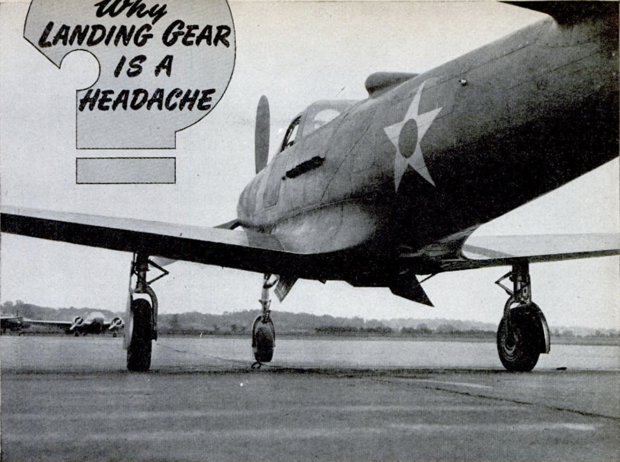
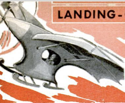
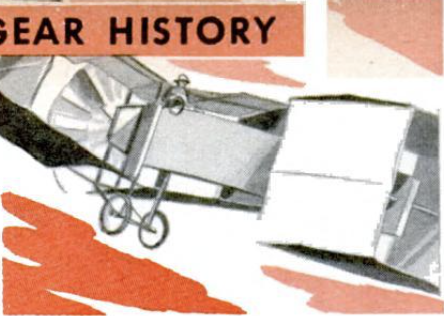
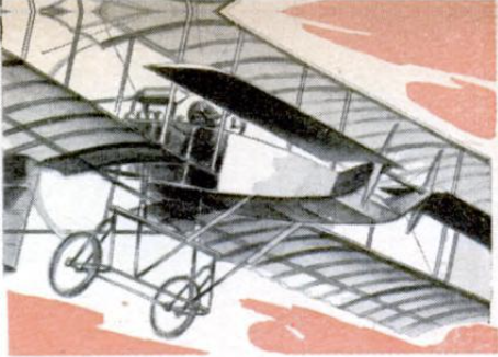
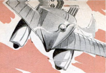
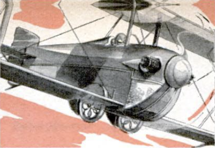
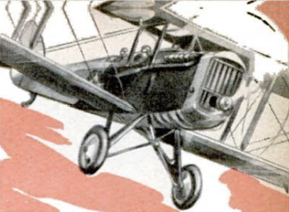
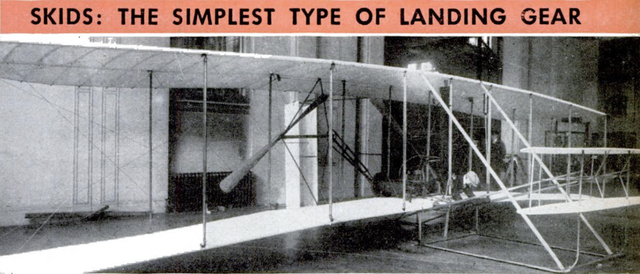
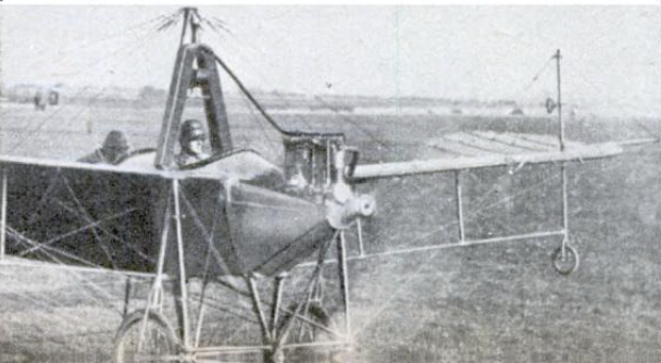
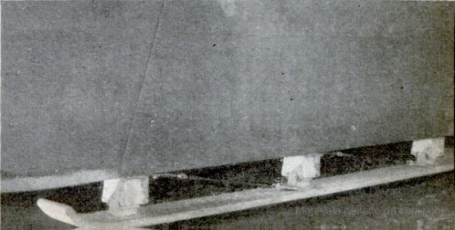
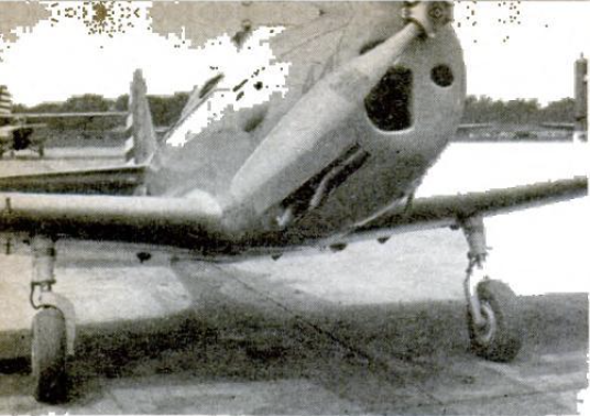
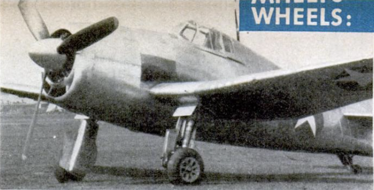
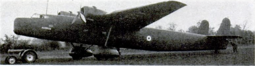
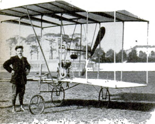
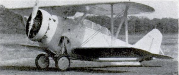
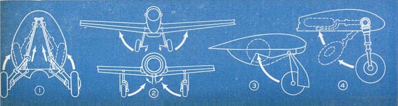
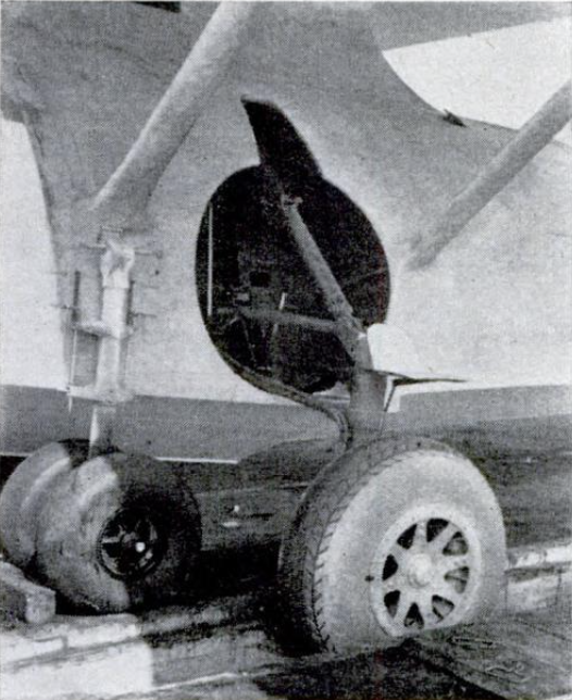
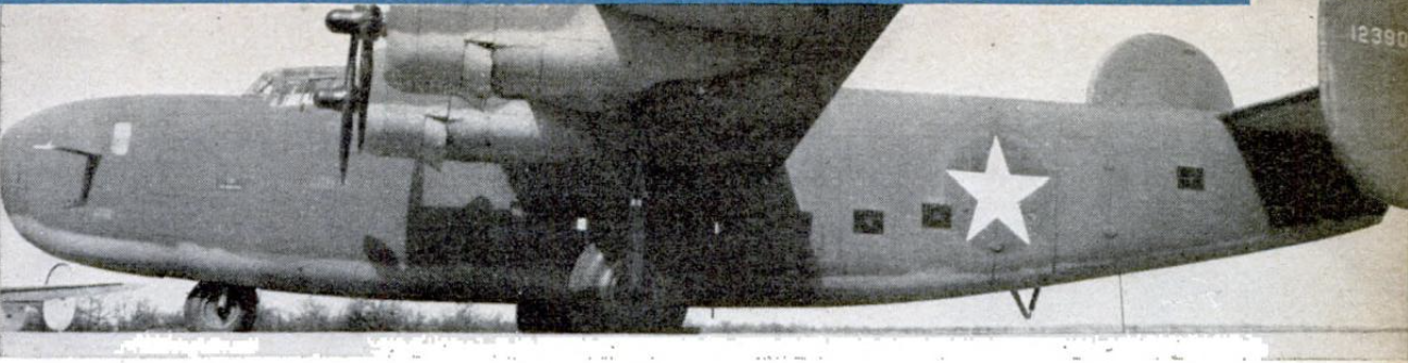
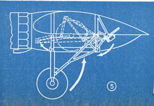
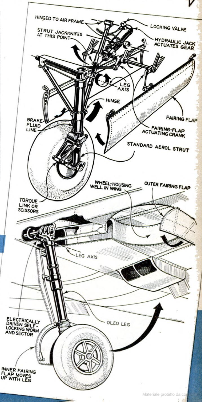
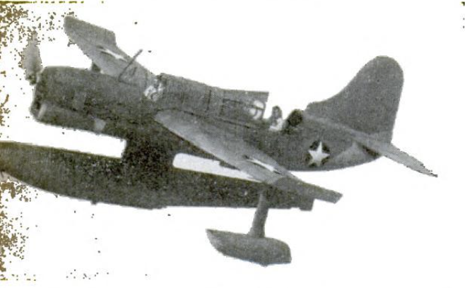
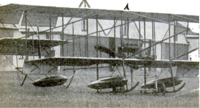
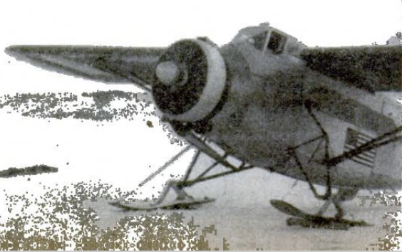
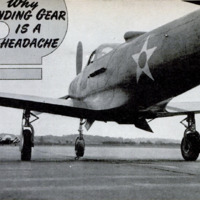 Immagine 2022-05-04 175329.png
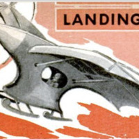 Immagine 2022-05-04 175345.png
 Immagine 2022-05-04 175359.png
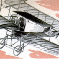 Immagine 2022-05-04 175607.png
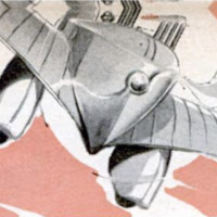 Immagine 2022-05-04 175622.png
 Immagine 2022-05-04 175634.png
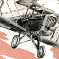 Immagine 2022-05-04 175645.png
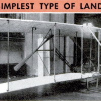 Immagine 2022-05-04 175702.png
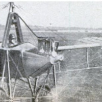 Immagine 2022-05-04 175904.png
 Immagine 2022-05-04 175914.png
 Immagine 2022-05-04 175923.png
 Immagine 2022-05-04 175942.png
 Immagine 2022-05-04 175955.png
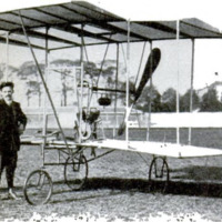 Immagine 2022-05-04 180011.png
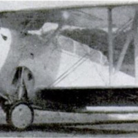 Immagine 2022-05-04 180023.png
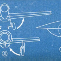 Immagine 2022-05-04 180036.png
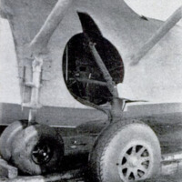 Immagine 2022-05-04 180048.png
 Immagine 2022-05-04 180105.png
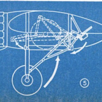 Immagine 2022-05-04 180120.png
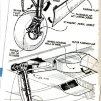 Immagine 2022-05-04 180142.png
 Immagine 2022-05-04 180228.png
 Immagine 2022-05-04 180244.png
 Immagine 2022-05-04 180304.png
 Immagine 2022-05-04 180324.png